95 S850 Operation & Maintenance Manual
ATTACHMENTS (CONT’D)
Installing And Removing The Attachment (Power Bob-Tach) (Cont’d)
Installing (Cont’d)
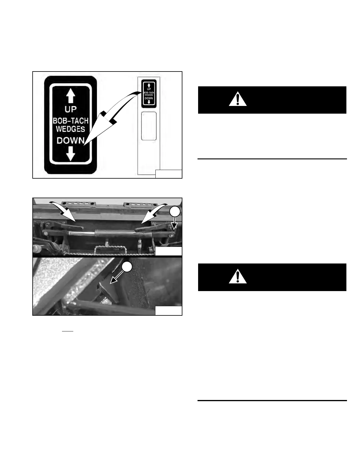
Figure 137
Figure 138
Push and
hold BOB-TACH “WEDGES DOWN” switch
(Right Switch Panel) [Figure 137] until levers are fully
engaged in the locked position [Figure 138] (wedges
fully extended through the attachment mounting frame
holes).
Both levers must contact the frame as shown when
loc
ked (Item 1) [Figure 138].
If both levers do not engage in the locked position, see
y
our Bobcat dealer for maintenance.
The wedges (Item 2) [Figure 138] must extend through
the holes in the mounting frame of the bucket (or other
at
tachment), securely fastening the bucket to the Bob-
Tach .
AVOID INJURY OR DEATH
The Bob-Tach wedges must extend through the holes
in the attachment mounting frame. Levers must be
fully down and locked. Failure to secure wedges can
allow attachment to come off.
W-2715-0208
Removing
Lower the lift arms and put the attachment flat on the
ground. Lower or close any hydraulic equipment, if
applicable.
If the attachment has electrical, water or hydraulic
conn
ections to the loader:
1. Stop the engine and exit the loader. (See STOPPING
THE ENGINE AND LEAVING THE LOADER on Page
88.)
AVOID INJURY OR DEATH
Before you leave the operator’s seat:
• Lower the lift arms and put the attachment flat on
the ground.
• Stop the engine.
• Engage the parking brake.
• Raise the seat bar.
• Move all controls to the NEUTRAL / LOCKED
position to make sure the lift, tilt and traction
drive functions are deactivated.
The seat bar system must deactivate these functions
when the seat bar is up. See your Bobcat dealer for
service if controls do not deactivate.
W-2463-1110
2. Disconnect attachment electrical harness and water
or hydraulic lines, if applicable, from the loader. (See
Relieve Auxiliary Hydraulic Pressure (Loader And
Attachment) on Page 73.)
Dealer Copy -- Not for Resale