Technical / Programming Manual
FT128 Rev 2.2
15
3 Control & Indicating Equipment
3.1 Technical Data
The specifications of FT128 Control Panel are shown in Table 1 below and the system
limitations are shown in Table 2 on the next page.
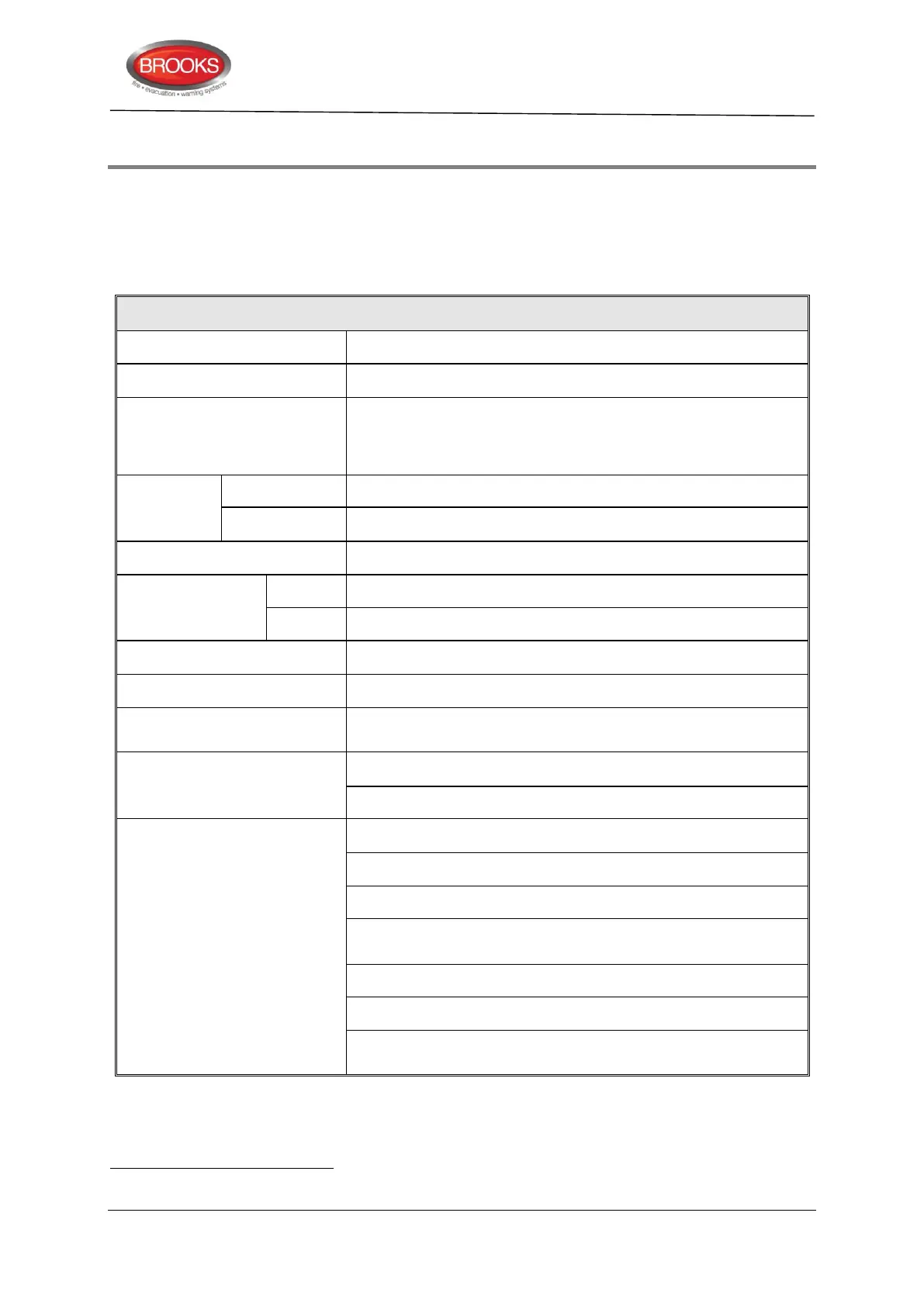
Table 1 Control Panel Specifications
Quiescent / alarm current is dependent on other equipment fitted
in FT128, type and number of expansion boards, connected
external equipment, etc. Refer to chapter "Current
Consumption”, page 168.
630 x 450 x 220 (including door)
920 x 450 x 220 (including door)
Oyster, powder coated ripple finish
Australian: Conform to AS7240-2, 7240-4 and AS4428.3
New Zealand: Conforms to NZS4512:2003
1 COM loop for 255 addresses.
2 programmable supervised voltage outputs S0-S1
1 programmable relay output R0
1 Non-programmable relay output for fault condition R1
1 programmable relay, driven via S0, 2 changeover contacts
available on the termination board.
RS232 Interface for Web-server 1598
Optional RS485 output for remote display units
Power supply (2 x 24 VDC) for Web-server, external equipment,
etc.
The rated output voltage is 24 VDC ± 1% for the main power source. Maximum ripple 240 mVp-p. The rated output voltage for
the second power source (backup battery) is 20-27 VDC.