Technical / Programming Manual
FT128 Rev 2.2
34
7. For supply air fan applications, set the post timing required to reset the duct detector
as follow:
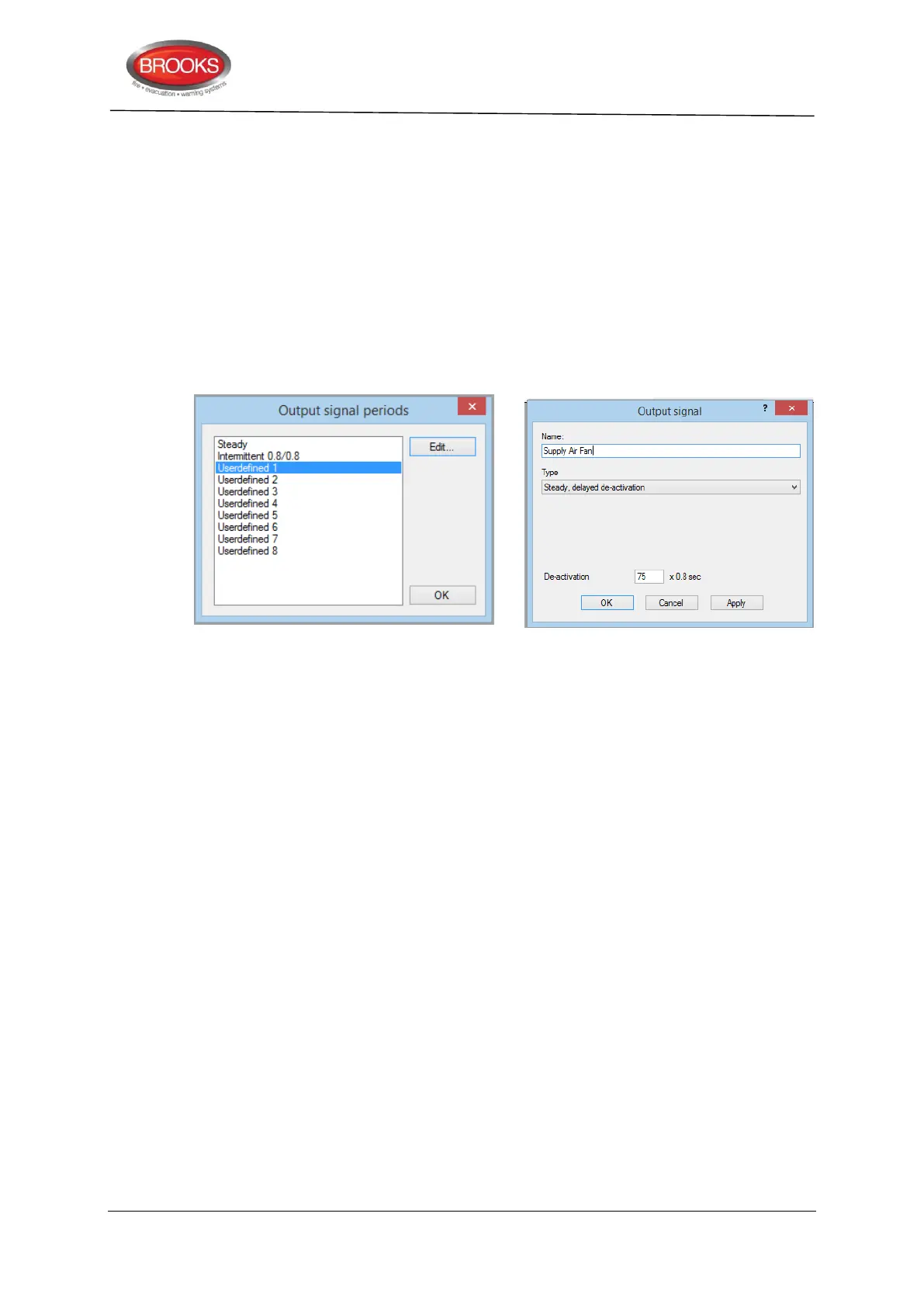
On the “System” tab, select “Output signal period”.
In the displayed dialog box shown below, select one of the “Undefined” options
Re-name the “Undefined” to Supply Air Fan then click edit.
On the drop down menu, select “Steady, delayed de-activation”
In the de-activation box, enter 75, this will set the post timing of the duct smoke
detector to 60 seconds i.e. the duct detector will reset after 60 seconds of clearing
up the smoke.
Click ok.
5.1.4 Fan Reset
A fan reset button is added to the front display of the fan control module to comply with the
requirements of AS1668.2 and used to independently reset 3361 relays Re0 and Re1 in
fire mode conditions. The two relays should be programmed in EBLWin to be “Latched” i.e.
resetting the alarm in the CIE will not bring the fans to the non-alarm condition until the
reset button is pressed. If the alarm remains active in the CIE, the fan reset button will not
function.
5.1.5 Fan Front Display
The fan control and display module is normally mounted in the CIE but it is also possible
to remotely install the module and connect it to the COM loop and 24V supply. The fan
operation is controlled by Re0 and Re1 relay outputs on the 3361 unit. The feedback signal
from the fan pressure switch is connected to the supervised input of 3361 to provide the
required indications of the fan status.
The typical front display of AS1668 module and connection diagram are shown in Figure
12, page 36.
Two typical fan application examples are shown in the following sections.
5.1.6 Supply Air Fan
A supply air fan is normally running in the non-fire mode condition and stops when smoke
is detected in the air supply duct, timing sequence is shown in Figure 10 below.