Technical / Programming Manual
FT128 Rev 2.2
38
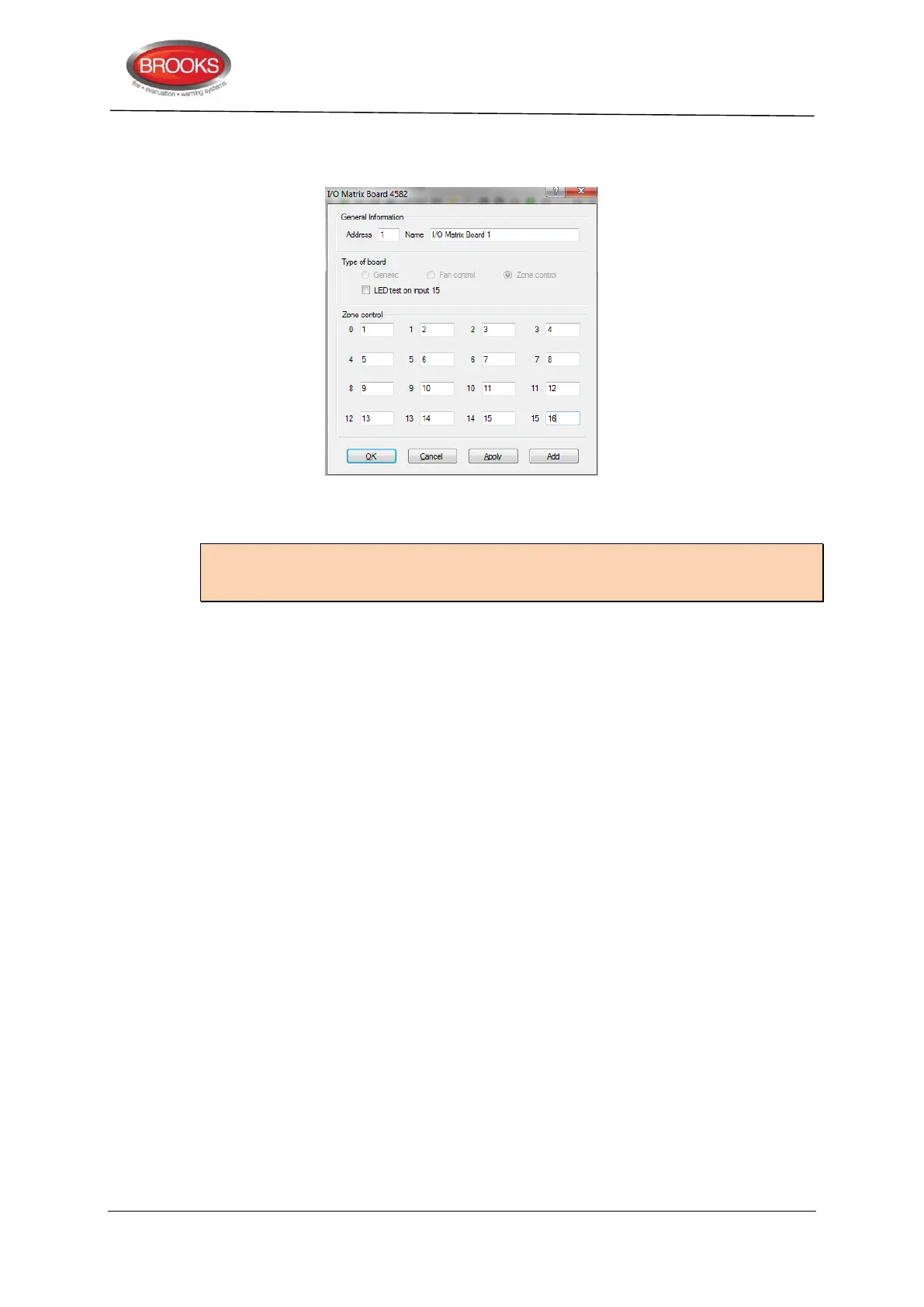
1. Right click on the COM loop and “Add I/O matrix board 4582” then select “Add zone
control”. The following dialog box will be showing.
2. Select the zone control module address (0-3) and zone control name (if required). If
the LED test function is required on input 15, tick the check box.
Note: The address selected in EBLWin (0-3) must match the address of the I/O matrix
board which is set by the jumpers JP1-JP3 as per Table 4 page 23. The type of board is
automatically selected.
3. Select the check box “LED test on Input 15” if this button is to be used for LED tests or
uncheck the box if LED test facility is not required.
4. Assign the zone number in the corresponding Zone control boxes.
5. Click OK.
5.3 Generic Applications
5.3.1 Overview
The generic feature in the FT128 software supports the remote mimic applications of the
I/O matrix board 4582. Currently, this feature is used in the New Zealand Fire Brigade
mimic and index panels as well as other products. This section describes one of the main
applications of the generic option, the popular NZ index panel. Refer to Brooks technical
datasheet TDS019 for other applications.
Each NZ master mimic board provides 12 LED indications and screw terminals for 4 inputs
(switches). The first 3 LEDs used for Common alarm (red), Normal (green) and Defect
(yellow). The remainder 9 LEDs (red) used to indicate separate zone indications or sprinkler
flow switch indication. Two of the four inputs are used to interface the NZ Fire Brigade
bulgin keys to the CIE. Additional slave mimic boards can be added to provide up to 36
additional red LED indicators.
Up to 4 mimic boards can be used to indicate maximum of 48 individual zone indications,
only one I/O matrix is required for every 4 mimic boards, up to two I/O matrix boards can
be used in the NZ mimic applications to provide 96 LED indicators, if no zone control
modules are used. Refer to drawing F702A for connection diagram. A typical NZ mimic
application is shown in Figure 15 below.