Technical / Programming Manual
FT128 Rev 2.2
171
25 Power Supply
Main power source
FT128 control unit is normally powered by 40W
Switching Power Supply, 230 V
AC
/ 24
V
DC
±1%, 1.8 A).
Standby power source
In case of mains failure i.e loss of 230 V
AC
, FT128 will be powered by back-up batteries,
i.e. two Sealed Lead-Acid batteries, 12V, 7-17 Ah.
See chapter “Current Consumption
Calculations” page 173 and Table 17, Table 18 and Table 19.
The batteries and the switch mode power supply are connected to the Main board (4556),
which also handles the charging of the batteries.
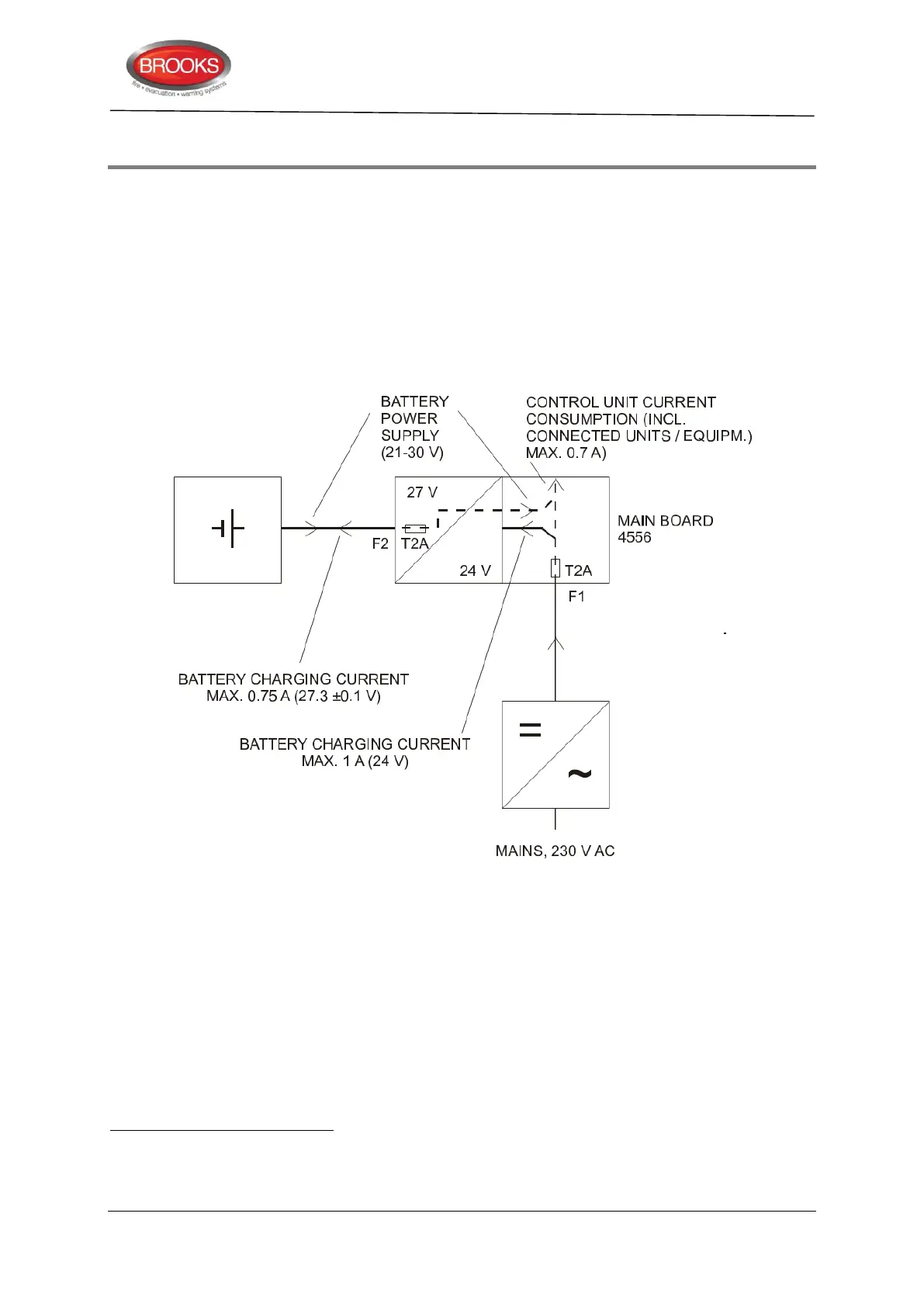
Figure 59 FT128 Power Supply Block Diagram.
In Figure 59, in the battery block, there is a slow blow glass fuse rated at 2A (3AG) in series
between the two batteries see also drawing F702A.
FT128 is a very flexible system. The number and type of loop units, the number and type
of display units, ext. equipment, etc. can vary from one control unit to another.
25.1 Charger Functions
According to AS7240.4, section 5.3.1 b), the charger shall be designed and rated so that
a battery discharged to its final voltage can be recharged to at least 80% of its rated
capacity within 24 hours and to its rated capacity within another 48 hours.
The standard Meanwel 40W power supply has been obsoleted. Currently 75W power supply is used.
7 - 17 Ah is depending on manufacturer. Specified "Final voltage" must be 10.5 V. NOTE! The batteries have to be ordered
separately.
POWER SUPPLY
230V AC / 24V DC
PSU CURRENT
MAX. 1.8A (24V) DC