Technical / Programming Manual
FT128 Rev 2.2
39
5.3.2 New mimic options
The new design of the mimic boards allows for either LED indicators or screw terminals for
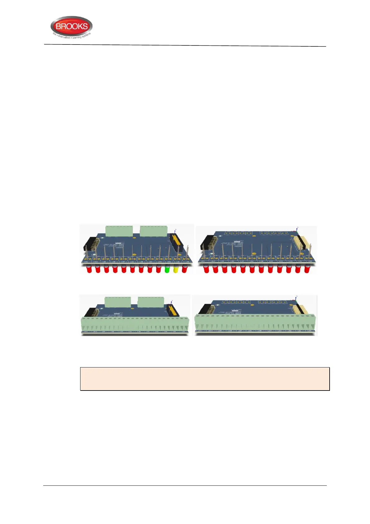
graphic or remote LED’s. Four new boards are now available as shown in Figure 14 below:
1. Master LED mimic Board SUB985: This must be the first board and to be fitted
with the I/O matrix board 4582. The boards contains the first 3 common indicators
and additional 9 red indicators. It also contain terminals to connect the Bulgin keys.
All outputs / inputs are fully programmable.
2. Slave LED mimic board SUB986: contains 12 fully programmable red indicators,
no provision for terminals or connectors for the I/O matrix. Up to 3 slave boards
can be connected to the master board via plug-in connectors.
3. Master terminals mimic board: In addition to the connector for the I/O matrix
board and Bulgin keys terminals, it also contain terminals to connect 12 remotely
located LED’s (no on-board LED’s). The I/O matrix board is to be fitted to this
master board. The board can be utilised to connect existing LED mimics to new
FT128 in retrofit applications.
4. Slave terminals mimic board: Up to 3 slave boards can be connected to the
master board via the plug-in connectors to provide terminals for additional 36
LED’s.
Master LED mimic board SUB985 Slave LED mimic board SUB986
Master Terminal mimic board SUB987 Slave terminal mimic board SUB988
Figure 14 Mimic Board Options
Note: Mounting holes of the new series of mimic boards are slightly different to the
mounting holes of the previous version (SUB927) i.e. new mimic LED boards must be
used in the new index cabinets.
5.3.3 Configuration and programming
The following procedures are used to configure the NZ mimic or index panel:
1. Select the COM loop then “Add I/O matrix board 4582” and select “Add generic”.
The following dialog box will appear.