Technical / Programming Manual
FT128 Rev 2.2
47
When the system sets in the normal condition, all LED indicators will be extinguished.
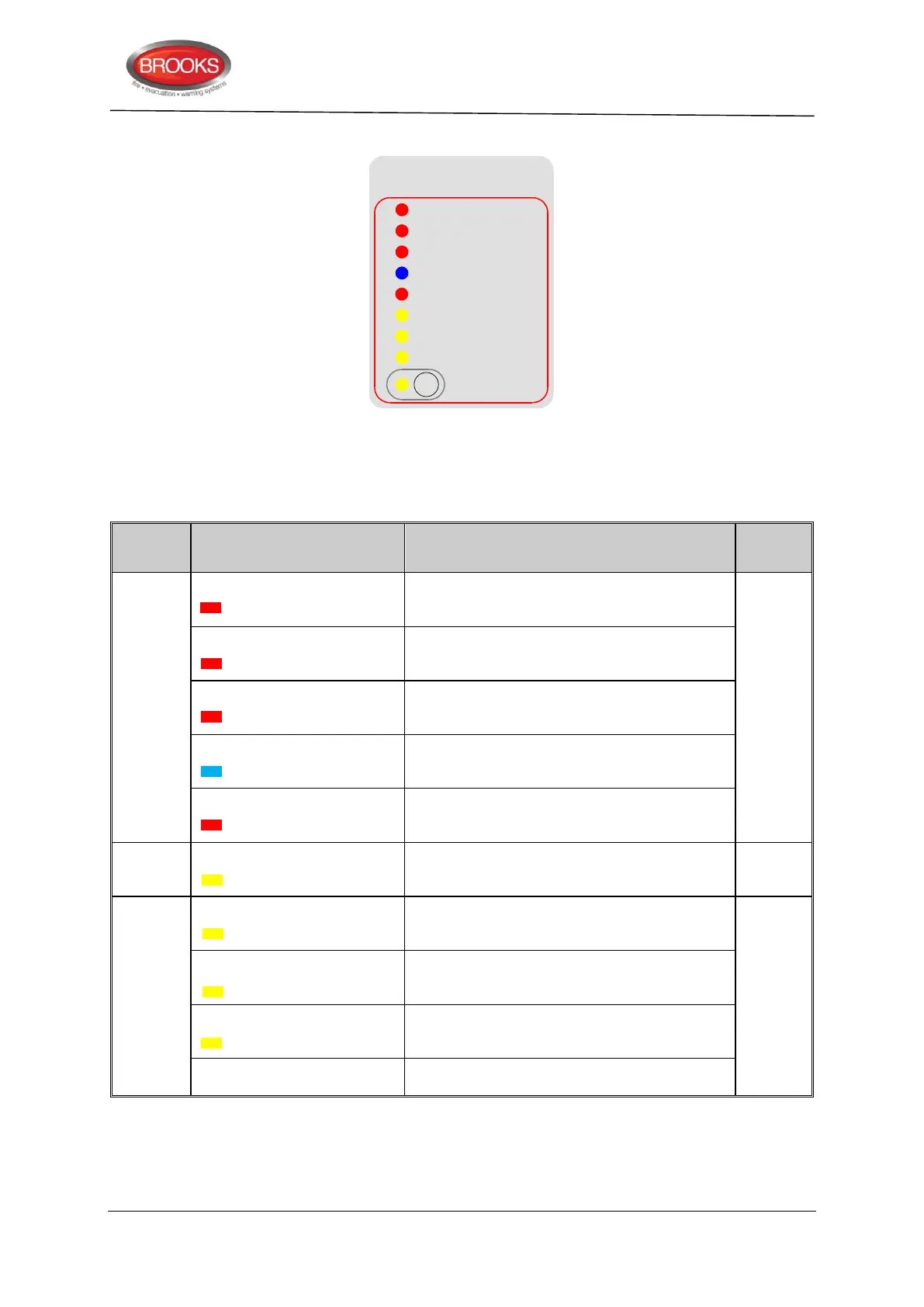
Gas Extinguishing
2nd Alarm -Timer Running
Gas Fault
Gas Discharged
Gas Initiated
Gas Disabled
1st Alarm
Gas Discharge Inhibited
Gas Externally Released
Service
Master Abort
Figure 21 Gas Extinguishing Display Layout
The gaseous extinguishing system status indicating LEDs and flash patterns are described
in Table 10 below. The default state of the LED indicators is OFF, if it is not defined below.
Table 10 Gas Front Status LED Indication and flash Pattern
One zone or zone address in alarm
2nd Alarm – Timer Running
Both zones or zone addresses in alarm
Gas release output activated
External gas release control activated
Gas discharged sensor input activated
Fault in any of the supervised inputs or outputs
Gas discharge inhibited via LCS isolate switch
Gas discharge disabled by the service master
abort switch or the gas lock-off valve controls
Illuminates when the master abort switch is
activated
Gas service master abort switch
5.5.3 Control board (SUB928)
The control board (SUB928) is mounted on top of the CIE interface board (SUB943) as
shown in Figure 22 below.