Technical / Programming Manual
FT128 Rev 2.2
29
Note: Jumper “JP6” is for future use.
Each I/O Matrix board has to be programmed via EBLWin according to its application.
Set the address on the 4582 via jumpers "JP1-JP3", see Table 4 page 23.
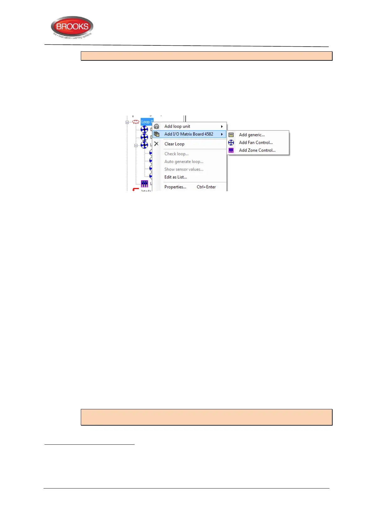
Right click on the loop and select “Add I/O Matrix Board 4582” to bring up the
context menu to select the type of Application Board to be added as shown below:
....and programmed for the following:
Address (must be the same board no. as set via jumpers "JP1-JP3").
Name (I/O Matrix Board # - normally not changed)
LED test on Input 15 (selected or not selected)
4.5 FT128 External Termination
In the Australian convention, the FT128 main board 4556 is mounted on the rear of the
front door. In order to avoid the field wiring termination on the swing door, an adapter board
SUB836
is added to the main board. The new version of the adapter board is plugged in
the screw terminals of the main board 4556 and interfaced to another external termination
board SUB835 mounted on the equipment plate. The adapter board SUB836 is connected
to the termination board SUB835 via ribbon cable.
The FT128 has only one programmable relay output. To increase the number of
programmable relays in the standard FT128 system, another relay with two changeover
contacts has been added to the termination board to provide 2 sets of additional relay
contacts
. This relay is controlled by the “Voltage output S1”
e.g. if S1 is programmed
for general alarm, the following will be available:
Voltage output S1 on CON 8
Change over alarm contacts R2-1 on CON 5
Change over alarm contacts R2-2 on CON 4
The PCB physical layout of the adapter board SUB836 is shown in Figure 8.
The PCB physical layout of the external termination board SUB935 is shown in Figure 9.
Note: As shown in Figure 8 and Figure 9, one physical PCB is used for both boards but
different components are fitted in each one.
The adapter board shown in Figure 8 and external termination board shown in Figure 9 use a new PCB revision (PCB250 Rev
5). In all previous revisions, the adapter board is soldered in the terminals of FT128 main board (4556) but the new PCB
revision has pins to screw in the terminal block on FT128 main board.
The additional alarm contacts can be used to trigger the OWS or for any other application.
The voltage output S1 terminals are still available on the termination board SUB835, please note, the current limitation of S1
is less than 200mA.