Technical / Programming Manual
FT128 Rev 2.2
37
5.2 Zone Control
The Zone Control Module provides a simplified indication of zone status without the need
for a liquid crystal display. The disable controls allow a specific zone to be temporarily
disabled without the need to access the CIE menu. This is typically used where building
works or maintenance procedures are being carried out in a localised area of a building.
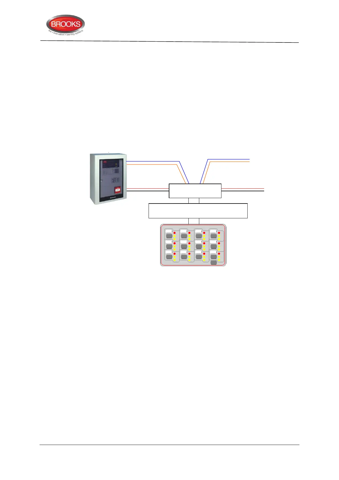
The front display layout is shown as part of Figure 13 below.
Only two zone control modules can be used in FT128, if no generic applications are used.
Each zone control module consists of a universal I/O matrix 4582 plugged in a display
board SUB900 specifically configured to provide up to 12 individual zone indicators and
controls. The module is normally mounted in the CIE. but it is also possible to connect the
module remotely via the COM loop and 24VDC supply.
Figure 13 Zone control application
5.2.1 Controls & Indications
Alarm LED (Red) – Illuminates when an alarm from a conventional zone, an addressable
device or group of addressable devices designated as a zone enters into an alarm state.
Fault LED (Amber) – Illuminates when either a short circuit or open circuit fault on a
conventional zone input or any fault that prevents an addressable alarm point in a
designated zone to operate properly.
Disabled LED (Amber) – Illuminates when a zone is disabled either by the disable switch
on the zone control card or where the zone is disabled via menu H2/B1.
Disable Switch – Pressing the disable switch will disable the specific zone selected.
Pressing the switch a second time will re-enable the zone. Functions are the same as menu
H2/B1.
LED Test Switch – Pressing the LED test switch illuminates all indicators if input 15 is
selected when programming the zone control function.
5.2.2 Zone Control Configuration
When the I/O Matrix board is selected in EBLWin to “Zone Control” type, up to 16 zones
[0-15] can be configured. The display Board is limited to only 12 zones and one additional
switch for LED test. The following procedures are used to configure the zone control
module:
or 24VDC from
external source
Zone Control & indicating board
SUB900
Disable DisableDisableDisable
Disable DisableDisableDisable
Disable DisableDisableDisable
LED
Test
DS DSDSDS
DS DSDSDS
DS DSDSDS
AL ALALAL
AL ALALAL
AL ALALAL
FT FTFTFT
FT FTFTFT
FT FTFTFT
ZONE CONTROL