Technical / Programming Manual
FT128 Rev 2.2
78
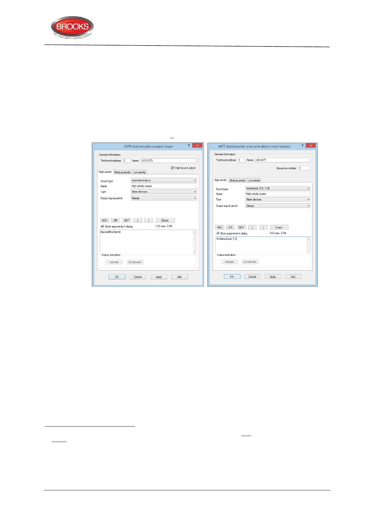
For each priority level:
Sound type (different for each priority level)
Name
Type (Normally "Alarm device")
Output signal period (Normally "Steady")
Control expression (with one or more trigger conditions)
If Enter arguments in dialog is selected, a separate dialog box is opened for easier
entering of the required data (e.g. zone, address, etc.). SSD size indicates how big the
control expression is. It must be < 80.
Figure 28 EBLWin 3379 and 4477 Dialog Box
Output test
When a PC is connected to FT128, EBLWin open and you are logged on, each output can
be tested for activation / de-activation.
9.1 Control Unit Outputs S0 – S1
FT128 has two programmable, supervised (monitored)
voltage outputs:
S0 Supervised voltage output, 24V
DC
, maximum 500 mA (Fuse F8).
S1
Supervised voltage output, 24V
DC
78
, maximum 200 mA (Fuse F6).
By default S0-S1 are set to type "Alarm device", "Intermittent 0.8 / 0.8, normally low,
supervised and trigger condition "General fire".
For connections and more information, see drawing F665.
Supervised as default but via EBLWin it is possible to set each output individually as non-supervised. A normally high output
cannot be supervised.
Supervised outputs have to be calibrated via menu H5/A1, see the FT128 Operation Manual. 1-5 supervision resistors 33K can
be used. The calibrated value has to be in the range 4K7-50K. A fault will be generated for a value outside this range. A
normally high output will be low for a few seconds during restart of FT128.
See Table 1 page 15 regarding system voltage.
S1 is also used to drive an ancillary relay on the FT128 termination board, refer to “FT128 External Termination”, page 29