Technical / Programming Manual
FT128 Rev 2.2
77
9 Programmable Outputs
FT128 has two programmable voltage outputs (S0-S1) and one programmable relay output
(R0). One or two 8 relay outputs expansion boards 4581 can be mounted in FT128. Input
and Output expansion board 4583 with three programmable outputs (Output 0-2) can also
be mounted in FT128. See “Expansion Boards ” page 22.
On the COM loop, an Addressable Multipurpose I/O unit 3361 with two programmable relay
outputs (Re0 and Re1) per unit and Addressable 2 voltage outputs unit 3364 with two
programmable voltage outputs (VO0 and VO1) per unit can be connected.
Addressable siren 4477, Addressable sounder base 3379, Addressable beacon 4380 and
Addressable Light indicator 4383 can also be connected on the COM loop, i.e. these units
have no physical output, only a siren, sounder and light respectively.
Notes: Units type 3379 + 4477 (or old type 3377) = maximum 50.
Units type 4380 = maximum 10
Each output is programmed (via EBLWin), when applicable for the following:
Name (Normally not changed)
Type
Signal period (continuous, pulse, delay, etc.)
Logic (NO / normally low or NC / normally high)
Supervised / Non-Supervised (The voltage outputs in FT128 and in the
Addressable 2 voltage outputs unit 3364)
Control expression (with one or more trigger conditions)
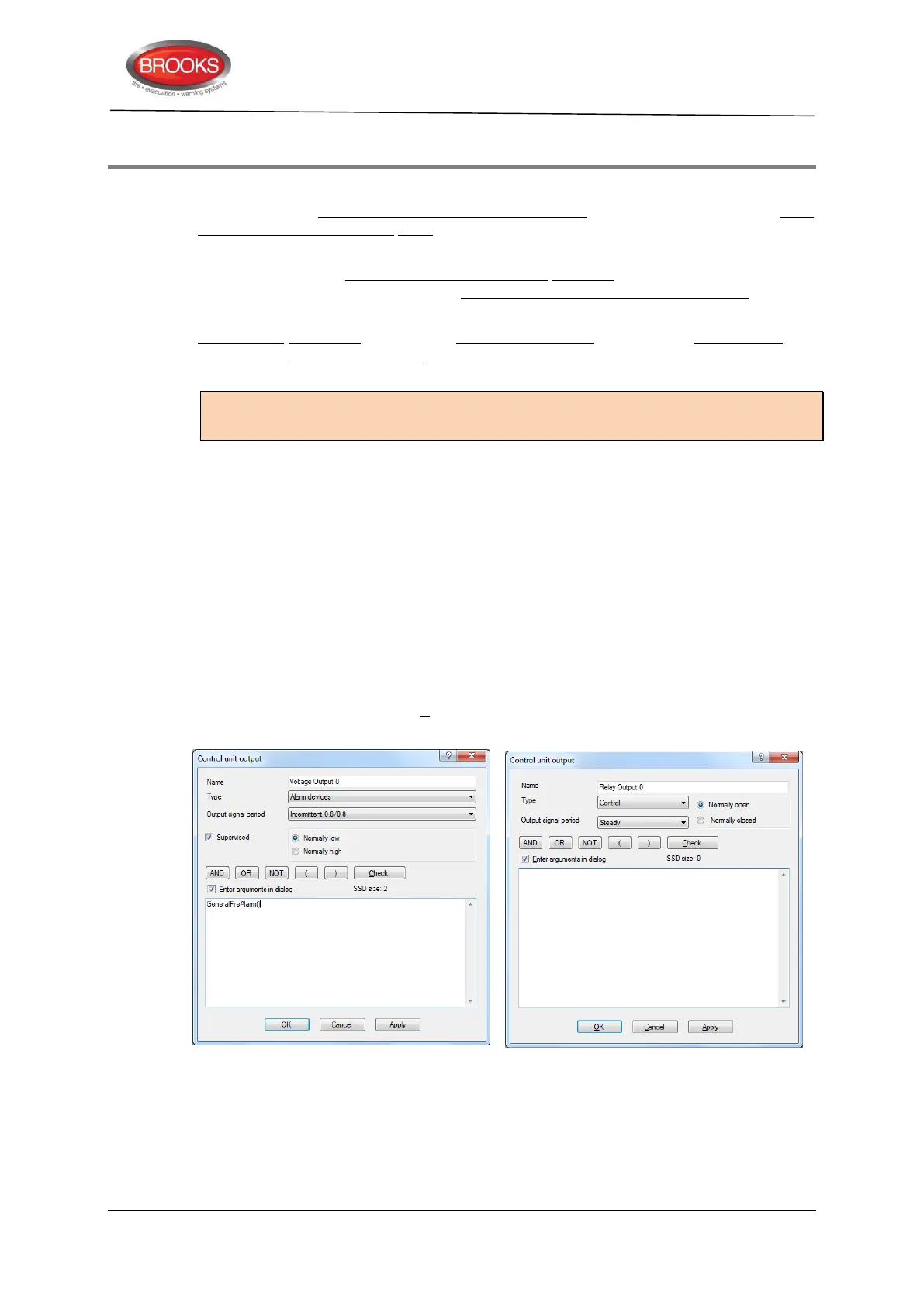
If Enter arguments in dialog is selected, a separate dialog box is opened for easier
entering of the required data (e.g. zone, address, etc.). SSD size indicates how big the
control expression is. It must be < 80.
Figure 27 EBLWin "Voltage" & "Relay” Output Dialog Boxes Respectively
Each 4477 and 3379 unit is programmed via EBLWin for the following:
Technical address
Name (Normally not changed)
Priority level (High / Medium / Low)