Technical / Programming Manual
FT128 Rev 2.2
32
2. In Auto mode, a fire alarm that controls the fan is activated.
In both cases, if the feedback signal confirming the change of state has not
been received by input In0 in 3361 within 30 seconds (default), the fan fault LED
will be lit.
If In0 is configured to be supervised and there is an open circuit fault in the input
wiring, the fan fault LED will also be lit.
Each Fan (0-3) (i.e. each Fan control) has to be added and programmed via EBLWin.
5.1.3 Configuration and Programming
For each fan, a field module (3361) is required and has to be configured in EBLWin as
“3361 I/O unit for fan control”. The AS1668 fans can be configured as follow:
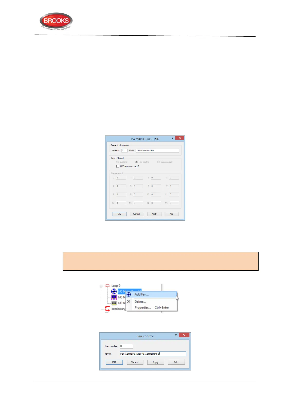
1. Right click on the COM loop and “Add I/O matrix board 4582”, the following dialog box
appears:
Select the I/O matrix board address (0-5) and change the name to “AS1668 Fan
Control”. If the LED test function is required, mark the check box “LED test on
input 15”.
Note: The address selected in EBLWin (0-3) must match the address of the I/O matrix
board which is set by the jumpers JP1-JP3 as per Table 4 page 23. The type of board is
automatically selected.
2. Right click on the configured “I/O Matrix Board” and select “Add Fan” as shown below
3. The Fan control dialog box appears for the 1
st
fan to be added. Repeat adding fans as
required, maximum 4 fans (0-3).