Technical / Programming Manual
FT128 Rev 2.2
59
beep. (Press "Read" again to double check), Instructions are on
the rear of the
tool.
3309 Label holder. To be mounted on the analogue base 3312 / 4313 / 3379
. Intended
for a label with "zone-address", "technical address", etc. to be read also when the
detector is plugged in its base. 100 label holders per packet, excludes labels.
3391 Labels for 3390. Packet with self-adhesive white labels for label holder 3390. 10
x A4-sheets, 132 labels for laser printer usage. The print-out is done via EBLWin.
6.1.2 Addressable I/O units
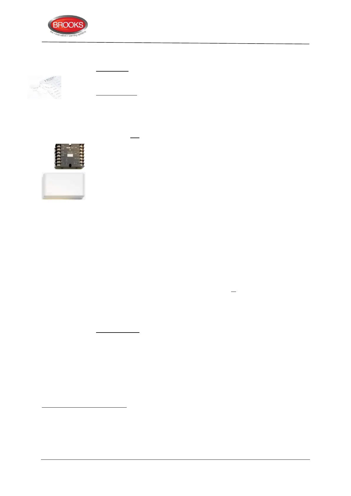
3361 Addressable multipurpose I/O unit
. COM loop powered unit.
The unit has two programmable inputs:
Monitored input
….used as Zone Line Input (Z) (terminals 6 & 7): End-Of-Line capacitor 10uF
mounted in the last unit on the zone line. A short circuit on the input can generate
a fault or a fire alarm (set via EBLWin). This input is intended for conventional
detectors.
Max. 1.5 mA, cable characteristic is max. 50 and max. 50nf.
….used as general input (In0) (terminals 5 & 7): An input for NC or NO contacts
(set via BLWin).
Isolated input (In1) (terminals 8 & 9): An optocoupler input (external 24 V
DC
/ 8
mA is required). Normally low or high (set via EBLWin).
The unit has two programmable relay
outputs:
Relay output (Re0): NC or NO contacts (set via EBLWin).
Relay output (Re1): NC or NO contacts (set via EBLWin).
Connections and examples, see drawings F733 and F735. The unit's dimensions:
90L x 70W x 32H mm. A plastic protection cover is attached. The cover's
dimensions: 129L x 73W x 45H mm.
The unit is intended to be surface mounted and for indoor use in dry premises.
When required, the unit can be mounted in a Waterproof box (IP66 / 67). The unit
has an LED to indicate communication to the unit or alarm condition. For more
information, see the Product Leaflet. The technical address is set with an Address
setting tool 3314/4414. The unit has an address label on which the programmed
technical address is to be written.
The Address setting tool is also used for mode setting:
NORMAL mode: Used for 3361 in FT128.
Also in the enclosed analogue heat detector 3309.
The same physical unit (3361) is also used in AS1668 Fan control applications and has a separate dialog box in EBLWin.
470nF is revised to 10uF.
It is via EBLWin possible to define this input function to be a manual call point ("Used as MCP"), i.e. it cannot be disabled via
a time channel, cannot included in two-unit dependence or cannot use the “AVF” function.
Relay contacts: maximum 2 A @ 30 V
DC
/ 125 V
AC
.