CFMOTO
05-142
5.6.4 Bevel Gear Washer Adjustment
When crankcase and/or bevel gears (in
pair) and/or bevel gear seat get replaced,
the washers must be adjusted.
CAUTION: Make sure the clearances
between gears and teeth are within a
appropriate range.
Bevel Gear Side Clearance
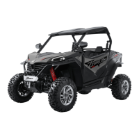
Install drive and driven bevel gear on
crankcase. Assemble crankcase with the
gasket placed. Install some bolts.
Insert a clean screw driver
1
through the
mounting hole
2
on MAG crankcase.
Insert it into the hole on drive bevel gear
bearing seat to fixate output driven gear,
which prevents drive bevel gear rotating.
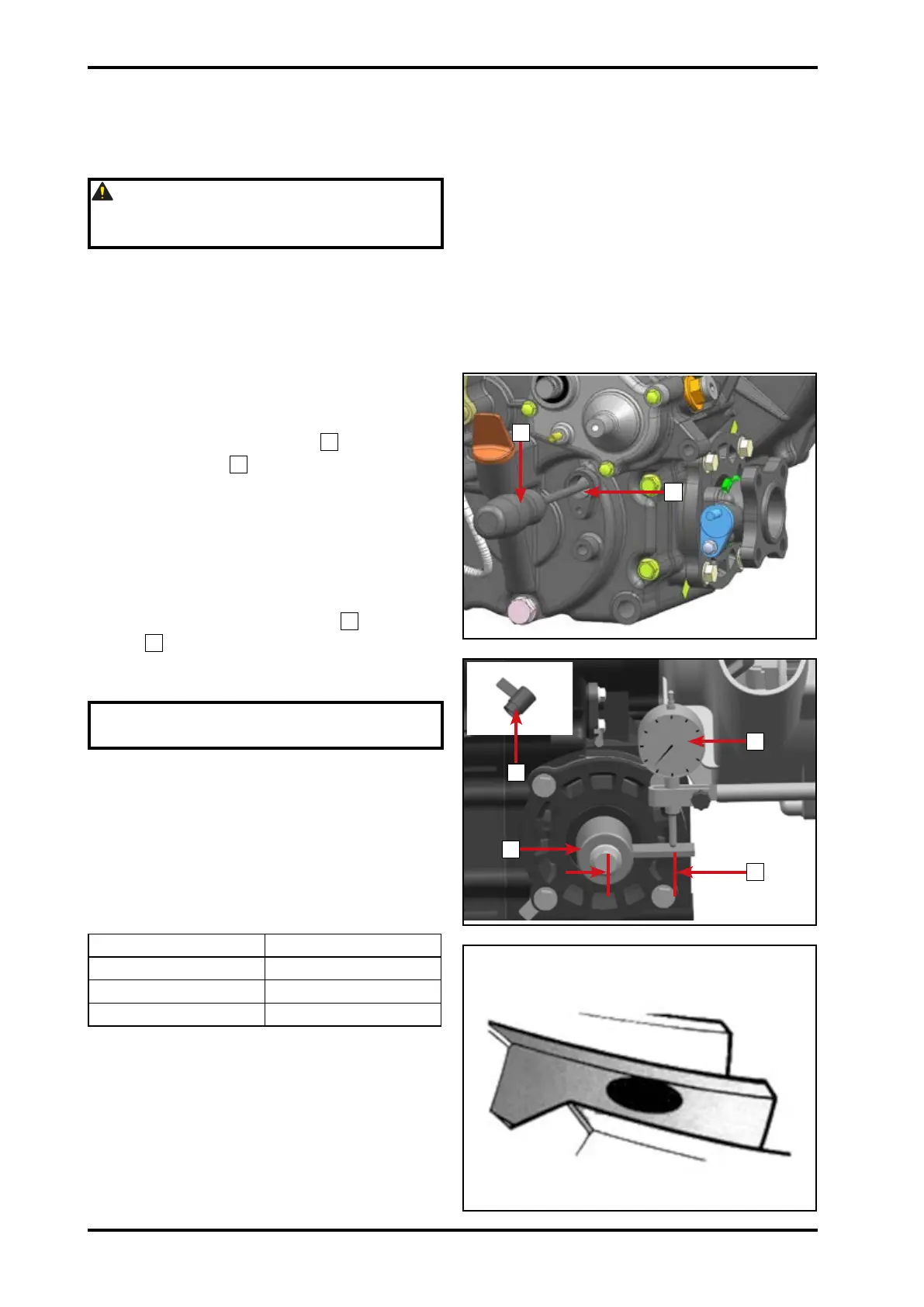
Install special tool: Bevel Gear Side
Clearance Measuring Tool
1
and dial
gauge
2
.
Rotate driven bevel gear shaft to measure
the side clearance.
NOTE: Measure at 4 points in the
perpendicular direction.
Adjust the thickness of driven bevel gear
washer if beyond standard. Repeat above
procedures until the clearance is qualied.
Bevel gear side clearance standard: 0.1
mm~0.2 mm
Adjusting Method
Side clearance Method
<0.1mm Increase thickness
0.1mm~0.2mm OK
>0.2mm Decrease thickness
Teeth Contact Condition Inspection
After adjustment, inspect teeth contact
condition:
Remove driven bevel gear from crankcase;
Clean the drive and driven bevel gear
teeth surface;
Dye driven bevel gear every tooth surface;
Install driven bevel gear.
A
1
1
2
1
2
059801
059802
059803
© CFMOTO Powersports, Inc. This manual is subject to all applicable copyright laws.
Reproduction or duplication in any form, whole or in part, is strictly prohbited.
 Loading...