12 Electrical System
12-39
Ignition coil parameter chart table:
Item Value
Unit
Min Standard Max
Stated Voltage 14 V
Running voltage 6 16.5 V
Resistance
(20°C~25°C)
Primary 0.74 0.76 0.78 Ω
Secondary 10.1 10.6 11.1 kΩ
Current 7 A
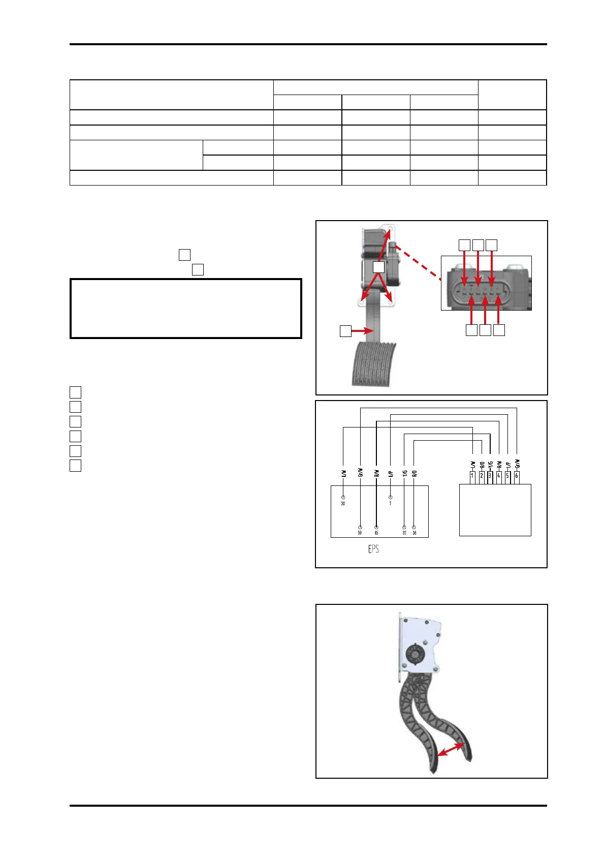
12.15 Electrical Throttle Pedal
Unplug all connectors before removing
electrical throttle pedal.
Remove three bolts
1
.
Remove throttle pedal
2
.
NOTE: Check whether the pedal is
installed in place. There is no foreign
body to block it. And it can rotate in
certain angles.
Pin functions:
A
.APS1
B
.GND1
C
.VCC1(+5V)
D
.VCC2(+5V)
E
.GND2
F
.APS2
Circuit connecting with ECU.
Electrical Throttle Pedal Inspection
Check circuit and connectors connection.
Pedal at 0°:
Voltage of analog signal output 1: 0.75V±0.1V
Voltage of analog signal output 2: 0.375V±0.1V
Pedal reaches limit position:
Voltage of analog signal output 1: 4.1V±0.2V
Voltage of analog signal output 2: 2.05V±0.2V
Installation
Reverse the removal procedures for
installation.
123201
Electrical throttle
pedal
123203
2
18°
1
B D F
A
C E
123202
© CFMOTO Powersports, Inc. This manual is subject to all applicable copyright laws.
Reproduction or duplication in any form, whole or in part, is strictly prohbited.










 To Next Page