05-143
05 Engine
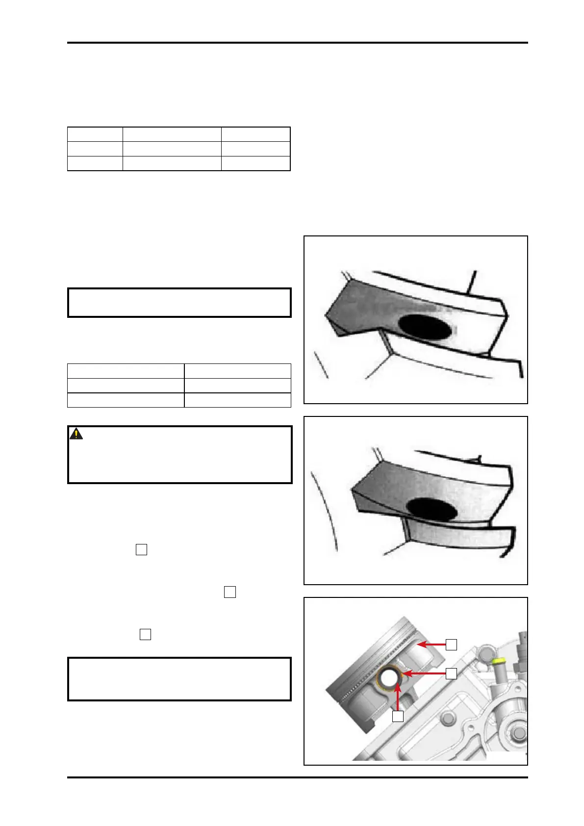
Rotate driven bevel gear several circles
forward and backward.
Remove drive and driven bevel gear assy
to see the dye coating results.
Status A On the top No
Status B In the middle Yes
Status C On the bottom No
If the teeth surface contact area is qualied
(Status B), continue following procedures.
If the teeth surface contact area is not
qualified (Status A or C), adjust the
thickness of drive bevel gear adjusting
washers. Repeat above procedures until
qualied.
NOTE: Clean the dye on gear teeth
after adjustment.
Adjusting Method
Contact condition Method
Status A Increase thickness
Status C Decrease thickness
CAUTION: After adjustment, measure
gear clearance again. If it is still not
qualified, replace drive and driven
bevel gear until it is qualied.
5.6.5 First Cylinder Body and Piston
Rotate crankshaft to make the rst cylinder
connecting rod exposed.
Install piston
1
.
During installation, the "▲" mark on piston
should face towards the transmission.
Apply engine oil on piston pin
2
and insert
it into piston pin hole and connecting rod
small end hole.
Install circlip
3
. (The open of circlip and
the groove should be staggered.)
NOTE: Install pistons according to
the made marks, to prevent incorrect
installation.
3
2
1
059901
059902
059903
© CFMOTO Powersports, Inc. This manual is subject to all applicable copyright laws.
Reproduction or duplication in any form, whole or in part, is strictly prohbited.