04 CVT System
04-39
2
1
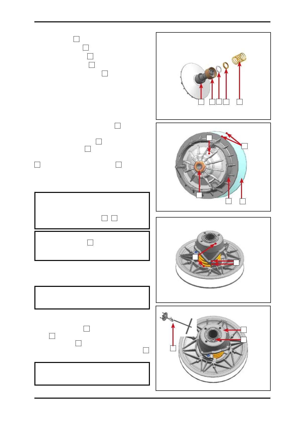
On the stationary sheave:
Install bearing
1
.
Install spring seat
2
.
Install steel washer
3
.
Install nylon washer
4
.
Install drive pulley spring
5
.
Place the stationary sheave
1
assembly
in a work bench vise.
Install moving sheave
2
assembly on the
stationary sheave
1
.
Compress the moving sheave assembly
2
then install drive pulley nut
3
(left-hand
thread).
Nut Torque: 180N•m~216N•m
NOTE: Align marks on moving and
stationary sheaves. Make sure the
marks of ramp plate, moving sheave
and stationary sheave
4
5
are on the
same line.
NOTE: When compressing drive pulley
moving sheave
2
, align the thrust
disc inner hex holes and drive pulley
stationary sheave mounting holes.
4.3.4 Driven Pulley Inspection
Disassembly
NOTE: Before disassembly of the
driven pulley, mark on the spring seat
mounting holes and slider positions.
Use special tool: Driven Pulley
Disassembly Tool
1
to compress the cam
plate
2
.
Remove circlip
3
with pliers.
Loosen Driven Pulley Disassembly Tool
1
slowly.
CAUTION: Spring is under pressure.
Use care when removing the special
tool to prevent injury.
54
3
21
3
2
1
4
2
1
3
040902
040901
040903
040904
5
© CFMOTO Powersports, Inc. This manual is subject to all applicable copyright laws.
Reproduction or duplication in any form, whole or in part, is strictly prohbited.










 To Next Page