User Interface
54
DX8210 Barcode Scanner
code cannot be decoded, a no read message is sent and the no read event is raised
at the end of the photoelectric sensor’s active phase.
2 Inputs Used
The reading phase is defined by 2 inputs. It starts when the Start Input is activated
and stops when the Stop Input is deactivated (unless the Extended Phase is
enabled).
Serial/ Network
In Serial/On-Line mode the reading phase starts when the Serial Start String is
received on the serial interface and ends when the Serial Stop String is received or
when a programmed Reading Phase Timeout expires.
If decoding is correct, the data is transmitted on the serial port as defined by the
configuration. The output line selected for the right output event is activated and
the relative message is transmitted on the serial interface or Ethernet input.
In case of a bad read, a no read message is transmitted on the serial interface. The
output line selected for the no read event is activated and the relative message is
transmitted on the serial interface or Ethernet input.
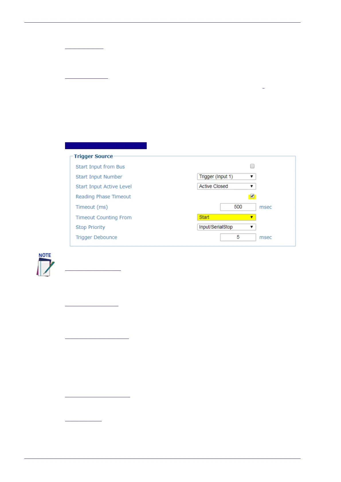
Trigger Source: 1 Input Used
Start Input from Bus
if checked, allows the Fieldbus Master to drive the Reading Phase. For Profinet or
Profibus interfaces, it allows the Fieldbus Master to drive the reading phase via bit 7
in Byte 0 (LSB) of the Output Area. For EtherNet/IP, it allows the EtherNet/IP Client
to drive the reading phase via bit 7 in Byte OutputBits of the DL_OutputStruct.
Start Input Number
Select the Input Number from the selections available in the drop-down list.
Options are; Trigger (Input 1), Aux (Input 3), or I/O 4 (Input 4)
This option defines the numbered input that will start the trigger cycle.
Start Input Active Level
Select Active Open or Active Closed from the drop-down list.
Active Open: The input is active when there is no current flowing through IN pins.
The input from the trigger source is normally closed. The scanner goes into trigger
mode when the input source is opened.
Active Closed: The input is active when current flows through IN pins. The input
from the trigger source is normally opened. The scanner goes into trigger mode
when the input source is closed.
Reading Phase Timeout
Select the check box to define a timeout for the On Line Serial mode and the On
Line 1 Input mode.
Timeout (ms)
Enter a timeout in milliseconds (from 40 to 15000 ms) in the field provided. The
Timeout represents the period of time for the reading phase.
The Start Input from Bus parameter is only available for Fieldbus Hosts.
 Loading...