D-Show Profile Guide110
Multiple Channels
In PFL or AFL mode, when multiple channels are soloed, the
left and right channels of the Solo bus are metered on the Se-
lected Channel meters, pre-Solo Trim control.
In SIP mode, when multiple channels are soloed, the Left and
Right Main bus meters are mirrored on the Selected Channel
meters.
Dynamics Key Listen
When Key Listen is activated, the left and right channels of
the Solo bus are metered on the Selected Channel meters,
pre-Solo Trim control.
Solo Clip Indication
When the Selected Channel meters are showing levels of a sin-
gle soloed channel, the clipping information on the meter
bridge LEDs mirrors that on the channel itself.
When the Selected Channel meters in the meter bridge are
showing Solo bus levels, the meter LEDs turn red to indicate
clipping on the Solo bus.
Metering Options
Meter Display
The following display options can be configured for D-Show
meters. These options affect all meters on the control surface,
including input, output, and ACS meters, as well as all
on-screen meters.
Meter Ballistics
Meters can be set to operate in the following modes:
RMS Mode (Default mode.) Meters follow the characteristics
of a damped analog meter. In this mode, the meter response
and decay is slower than in Peak mode, providing an average
reading of the metered signal. A single LED shows the peak
level for the designated Peak Hold Time.
Peak Mode Meters follow the characteristics of a standard
peak meter. In this mode, the meter response is instanta-
neous, showing the true peak level of the metered signal.
Peak Hold Time
Peak Hold Time can be set within a range of 0–20 seconds.
To set the Peak Hold Time:
1 Go to the Options page and click the Interactions tab.
2 Under Meter, enter a value for the Peak Hold Time.
3 Press Enter on the keyboard.
Clipping Indication
D-Show meter clip indicators are proximity warnings that
show when an input or output signal reaches or exceeds the
configured Clip Margin.
Clipping is indicated by all of a meter’s LED segments turning
red. The LEDs stay red for the designated Clip Hold Time.
Clipping can occur at several points throughout the signal
chain. A clip at any one of these points is indicated on the
meter. For more information on the location of D-Show clip
detect points, refer to Chapter 26, “Signal Flow Diagrams.”
Clip Margin
The Clip Margin setting lets you configure the amount of
headroom you want before clipping indication begins. Clip
Margin is expressed as dB below maximum (where maximum is
a peak level of +20 dBVU).
Clip Margin can be set within a range of 0 dB to 30 dB below
maximum, and is configured separately for inputs and out-
puts.
To set the Clip Margin:
1 Go to the Options page and click the Interaction tab.
2 Under Meter, enter values for Input Clip Margin and Output
Clip Margin.
3 Press Enter to confirm the setting.
Clip Hold Time
The Clip Hold Time determines how long a clip indication
lasts after the last clipped signal. Clip Hold Time can be set
within a range of 0–20 seconds.
To set the Clip Hold Time:
1 Go to the Options page and click the Interaction tab.
2 Under Meter, enter a value for the Clip Hold Time.
3 Press Enter to confirm the setting.
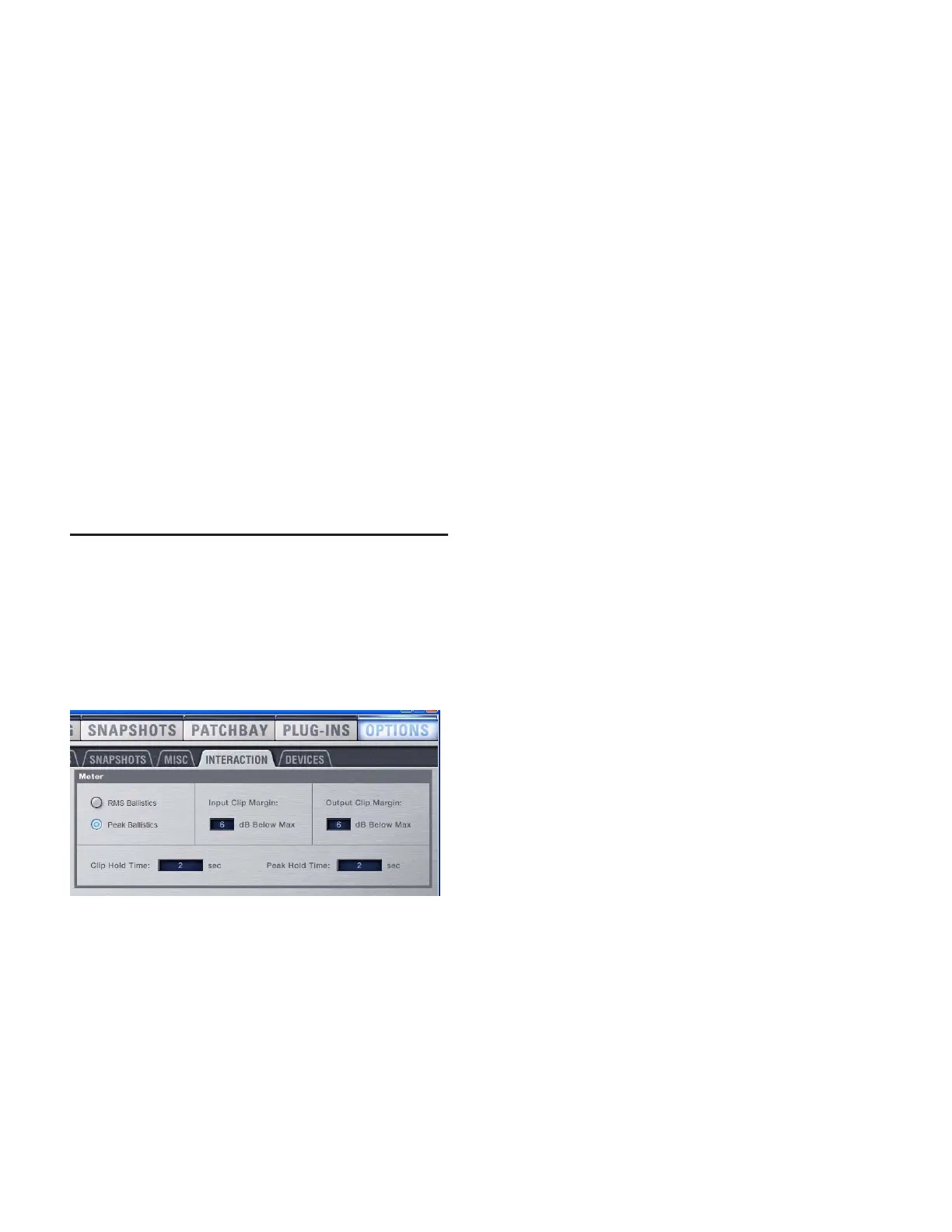
Metering options in the Interactions tab of the Options page