D-Show Profile Guide240
GPI Output Connector Pin Assignments
The D-Show Profile GPI Output is a female DB-25 connector.
:
DB25F Pinout
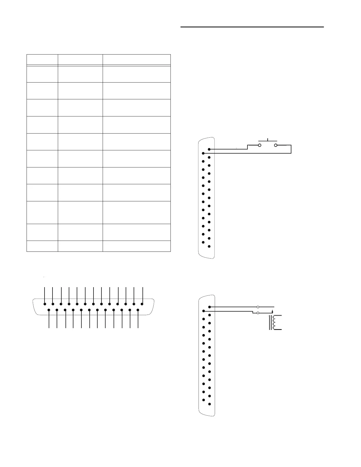
GPI Wiring Diagrams
The following diagrams provide examples of GPI pinout and
wiring for the common uses. All diagrams are shown from the
rear (solder side) of the DB25 connector.
GPI Input Examples
The following diagrams provide simplified wiring examples
for a customer-provided DB25 female connector, to attach to
the male GPI In connector on D-Show Profile.
Wiring a Switch to Drive GPI
Wiring a Relay to Drive GPI
GPI Output Connector Pin Assignments
Pin Number Function Comments
1, 14 Output 1 Floating contact closure out-
put
2, 15 Output 2 Floating contact closure out-
put
3, 16 Output 3 Floating contact closure out-
put
4, 17 Output 4 Floating contact closure out-
put
5, 18 Output 5 Floating contact closure out-
put
6, 19 Output 6 Floating contact closure out-
put
7, 20 Output 7 Floating contact closure out-
put
8, 21 Output 8 Floating contact closure out-
put
12, 13, 24,
25
+12V auxiliary
power
Maximum total load 200 mA
All +12V pins are connected
together internally
9, 10, 22,
23
Ground for auxil-
iary power
All ground pins are con-
nected together internally
11 Reserved Do not use
Pinout for D-Show Profile DB25F GPI Output port (looking at back of
console)
12345678910111213
141516171819202122232425
No ground reference needed
between systems.
1
14
DB25F
No ground reference needed
between systems.
1
14
DB25F