Chapter 2: Configuring and Connecting D-Show 9
7 Place the Trackball Mount in position so that you can feed
the T-bolts through the two slots on the lip of the Trackball
Mount.
8 Move the Mount and T-bolts left or right to line up the
opening in the mount with the front panel USB and Head-
phone ports.
9 Tighten the lock nuts to secure the assembled Trackball
Mount to the console.
10 Reconnect USB and headphones to the front panel ports.
Removing and Attaching the Trackball Mount
The Trackball Mount can be removed quickly before packing
or storing the console.
To remove the Video Monitor Mount:
1 Holding the Trackball Mount in one hand, loosen the lock
nuts that secure it to the front of the console.
2 Drop the Trackball Mount off track to remove the entire as-
sembly from the console.
3 Replace the lock nuts onto the T-bolts and tighten them
down, to secure them in place.
To attach the assembled Trackball Mount to the console:
1 Loosen the two lock nuts securing the T-bolts in place, along
the extrusion at the front of the console.
2 Position the Trackball Mount so that its base slots line up
with the T-bolts, and slide the Trackball Mount into position.
3 Tighten the lock nuts to secure the mount into place.
Back Panel Connectors
FOH Link
FOH Link connects D-Show Profile to the FOH Rack. One FOH
Link cable is included with each FOH Rack.
VGA
A single, female VGA connector is provided for driving a com-
patible video display (not included).
CAN Bus
This XLR3-M connector is not functional.
Footswitch 1 and 2
Two female 1/4-inch TS footswitch jacks are provided for
switch input. Footswitches can be normally open or normally
closed, latching or momentary. Functions are assigned to
these jacks on-screen in the Options > Events page.
GPI Input Port
A 25-pin, female D-Sub connector that provides a total of 8
General Purpose Interface (GPI) Inputs.
GPI Output Port
A 25-pin, male D-Sub connector that provides a total of 8 Gen-
eral Purpose Interface (GPI) Outputs.
USB Port
A single USB 1.1 Type A port is provided on the back panel for
interfacing with iLoks, keyboards, pointing devices or key
disks.
Console Lights
Two XLR3-F jacks to connect to the included console lights.
Power
Two male, 3-pin IEC power sockets with cable retaining clips
are provided, one for each of the internal power supplies. Two
North American standard IEC power cables are provided with
each D-Show Profile console.
Always disconnect USB and headphones from the front
panel ports before removing or attaching the Trackball
Mount.
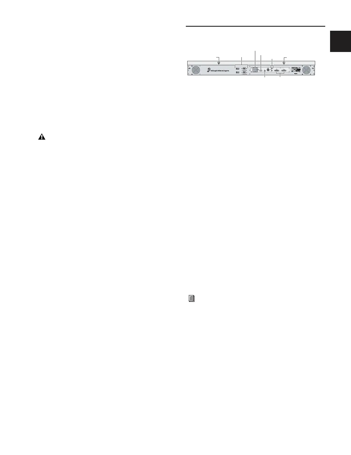
D-Show Profile back panel and connectors
For specifications, wiring diagrams and pinouts, see
Chapter 29, “Control Surface Reference.”
FOH Link
VGA
Footswitch
GPIUSB
Console Lights
Power
Console Lights