Chapter 8: Outputs and Output Routing 73
Setting the Hardware Insert Location
You can choose the location of the hardware insert in the sig-
nal path, relative to the four plug-in inserts, for each channel.
A hardware insert does not need to be currently assigned to do
this.
To set the hardware insert location:
1 Go to the Outputs page and select the channel where you
want to set the hardware insert location.
2 In the Inserts section of the Outputs page, click the hard-
ware insert indicator so that it lights red.
Activating and Bypassing Inserts
After hardware and plug-in inserts are assigned to an Output
bus, they can be activated and bypassed from the console or
the corresponding Output page controls.
To activate or bypass an Output bus insert:
1 Target the bus by pressing its Select switch.
2 Press any of the Plug-In switches, or click the HW in/out
switch on-screen, to activate or bypass the corresponding In-
sert. The switch lights when the Insert is activated. (Hardware
inserts cannot be bypassed from D-Show Profile; use the
on-screen control instead.
Inserting the Built-In Graphic EQ on
Output Busses
A built-in 31-band Graphic EQ can be inserted on any of the
following Output bus types: Mains, Groups (or Variable
Groups), Auxes, Matrixes, and PQs. A maximum of 24
Graphic EQs are available, depending on the how they are
configured in the System Configuration Options.
For more information on configuring and using Graphic EQs,
see “Graphic EQ for Outputs” on page 139.
To insert a Graphic EQ on an Output bus:
1 Target the bus by pressing its Select switch.
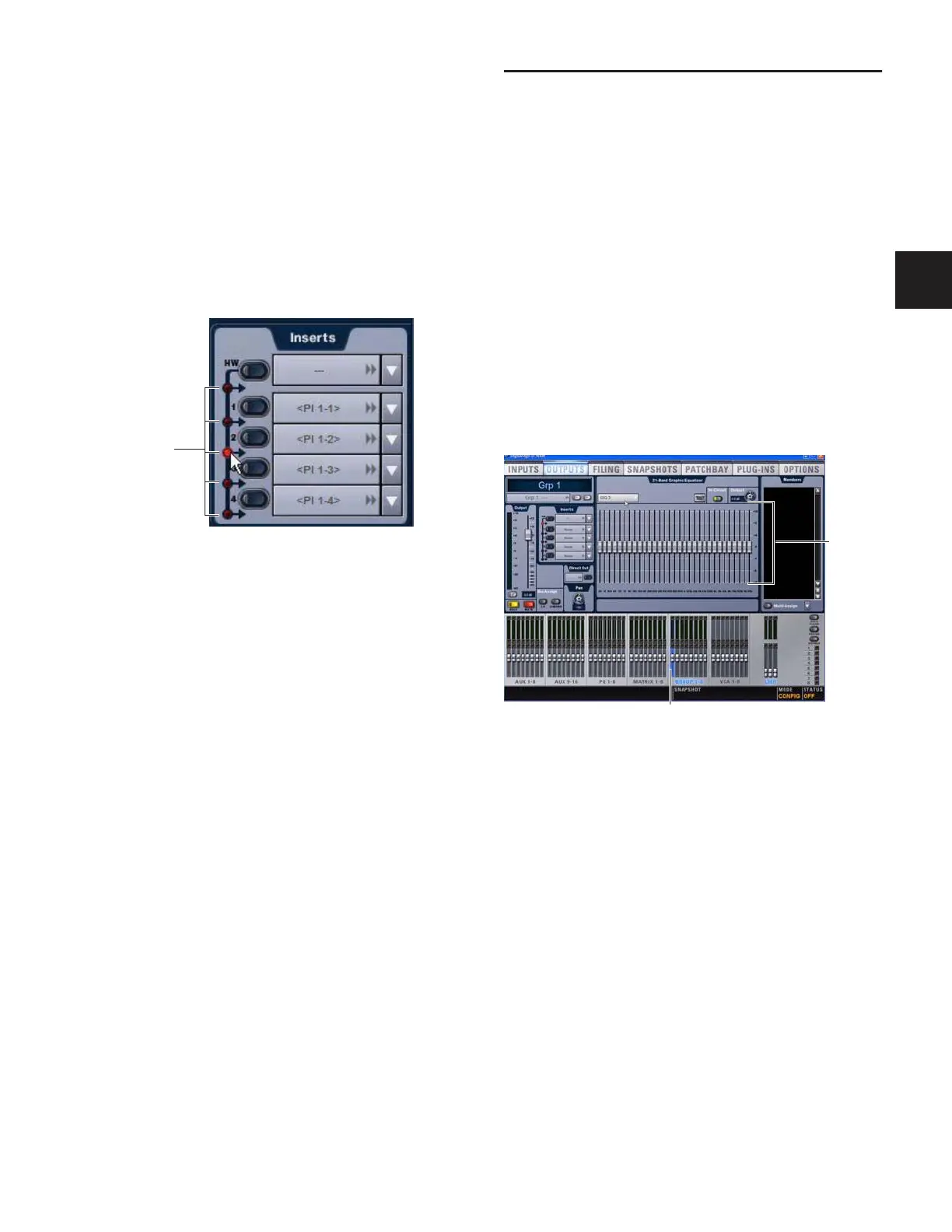
2 In the Outputs page, click the Graphic EQ tab.
3 Click the Graphic EQ pop-up menu and choose an available
mono or stereo Graphic EQ. The entire Graphic EQ is dis-
played on-screen.
Setting a hardware insert location in the Inputs page
Click to set
HW Insert
location
Graphic EQ displayed in the Outputs page
Output bus selected (Group 1)
Graphic
EQ
Faders