Chapter 29: Control Surface Reference 239
GPI Input Connector Pin Assignments
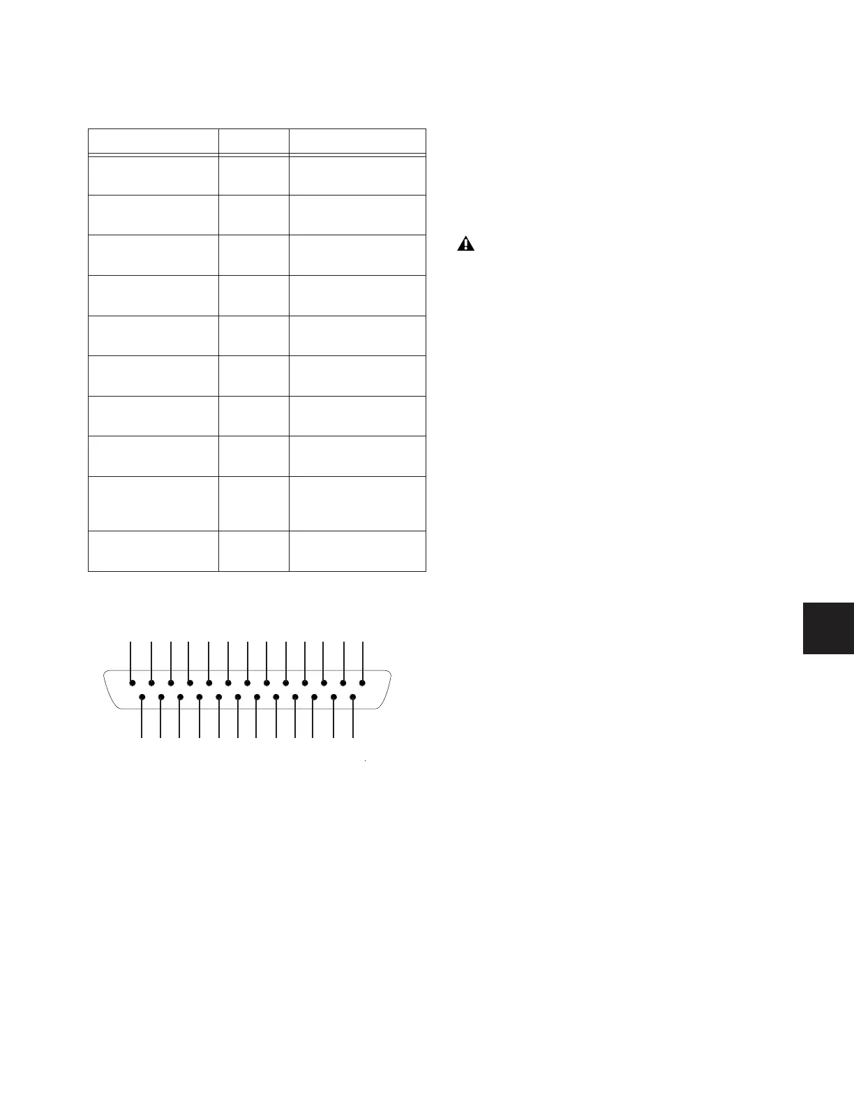
The D-Show Profile GPI Input is a male DB-25 connector.
Pinout for GPI Input Connector
GPI Output Specifications
A 25-pin, female D-Sub connector provides a total of 8 Gen-
eral Purpose Interface (GPI) Outputs.
• Outputs are isolated, floating relay contacts (contact clo-
sure).
• Switched voltage is 200V max; 0.5A max.
• Switched voltage with respect to safety/chassis ground is
300V max.
GPI Output Power Specification
The GPI Output connector also provides +12VDC at up to 200
mA for powering external devices, such as relays or LEDs. The
ground return that is provided is the D-Show Profile internal
system ground, which is connected to AC safety ground.
GPI Output Ground Connections
The GPI Outputs provided are isolated contact-closure style.
Each GPI output is presented on a pair of pins (see “GPI
Output Connector Pin Assignments” on page 240). These two
pins represent the two sides of a switch that can be opened
and closed. If it is desired to drive a signal to ground, then one
of the pins must be wired to ground, and the other to the
signal to be controlled.
GPI Input Connector Pin Assignments
Pin Number Function Comments
1 Input 1 Logic level (TTL, CMOS)
input with pullup
2 Input 2 Logic level (TTL, CMOS)
input with pullup
3 Input 3 Logic level (TTL, CMOS)
input with pullup
4 Input 4 Logic level (TTL, CMOS)
input with pullup
5 Input 5 Logic level (TTL, CMOS)
input with pullup
6 Input 6 Logic level (TTL, CMOS)
input with pullup
7 Input 7 Logic level (TTL, CMOS)
input with pullup
8 Input 8 Logic level (TTL, CMOS)
input with pullup
14, 15, 16, 17, 18,
19, 20, 21
Ground All ground pins are con-
nected together inter-
nally
9, 10, 11, 12, 13, 22,
23, 24, 25
Reserved Do not use
Pinout for D-Show Profile DB25M GPI Input port (looking at back of
console)
12345678910111213
14 15 16 17 18 19 20 21 22 23 24 25
The D-Show Profile GPI Outputs can switch 500 mA max-
imum. This applies even to short term current surges. This
limit can be exceeded when driving a capacitive or incan-
descent lamp load. An incandescent lamp may draw as
much as ten times its steady state current when first turned
on. Therefore such lamps are typically not appropriate
loads for the GPI Outputs, and should instead be controlled
by a secondary relay.