DESCRIPTION TORQUE
TIRE AND WHEEL:
Wheel Mounting Nut 109–150 N·m (80–110 ft.
lbs.)
INTEGRATED CONTROL UNIT:
Mounting Bolts (to
Bracket)
11 N·m (97 in. lbs.)
CAB Mounting bolts 2 N·m (17 in. lbs.)
Bracket-to-Frame Rail
Bolts
23 N·m (200 in. lbs.)
WHEEL SPEED SENSOR:
Head Mounting bolt 12 N·m (105 in. lbs.)
BRAKE FLUID LEVEL SWITCH
DESCRIPTION
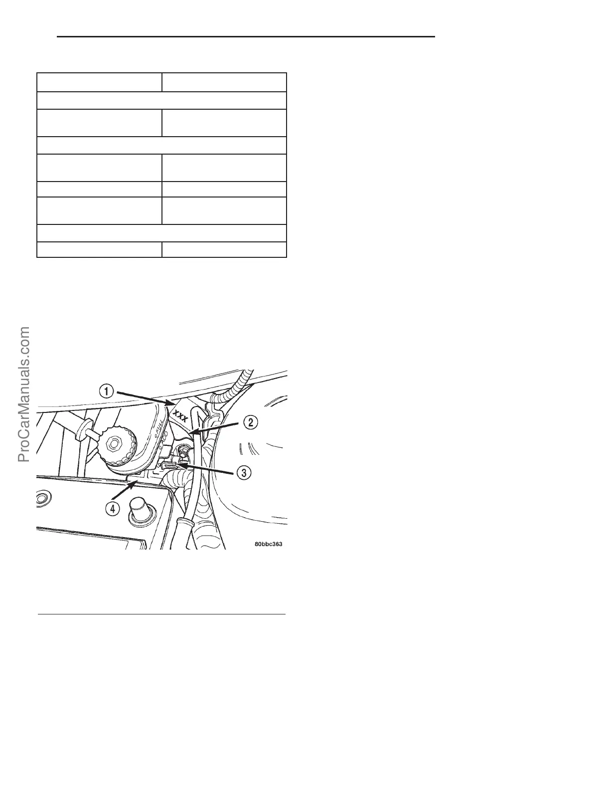
The brake fluid level switch is located in the left
side of the brake fluid reservoir on the master cylin-
der (Fig. 3). It is clipped into the reservoir. It can be
removed from the reservoir and replaced if necessary.
OPERATION
The purpose of the brake fluid level switch is to
provide the driver with an early warning that the
brake fluid level in the master cylinder reservoir has
dropped below an acceptable level.
As the fluid drops below the designed level, the fluid
level switch closes and grounds the red BRAKE warn-
ing indicator circuit. This turns on the red BRAKE
warning indicator. At this time, the master cylinder
brake fluid reservoir must be checked and filled to the
full mark with DOT 3 brake fluid. Check the entire
brake hydraulic system for evidence of a leak.
CAUTION: An abnormal loss of brake fluid in the
master cylinder fluid reservoir could be caused by a
leak in the hydraulic system. The entire brake
hydraulic system should be checked for evidence
of a leak.
HYDRAULIC/MECHANICAL
OPERATION - DRUM BRAKES (REAR)
When the brakes are applied, fluid pressure is sent
to each rear drum brake wheel cylinder. The pressure
at the wheel cylinder is exerted equally against both
cylinder pistons. The piston pressure is transmitted
directly to the top of each brake shoe. This forces the
shoes out against the inner surface of the brake drum.
This causes friction, bringing the vehicle to a stop.
When the brake pedal is released, so is the fluid
pressure. The return springs attached to the shoes
return the shoes to the released position.
Vehicles with rear drum brakes use the drum
brakes as part of the parking brake system also.
Refer to Parking Brake for additional information.
BRAKE PADS/SHOES-FRONT
CLEANING - DISC BRAKE SHOES
WARNING: DUST AND DIRT ACCUMULATING ON
BRAKE PARTS DURING NORMAL USE MAY CON-
TAIN ASBESTOS FIBERS FROM PRODUCTION OR
AFTERMARKET BRAKE LININGS. BREATHING
EXCESSIVE CONCENTRATIONS OF ASBESTOS
FIBERS CAN CAUSE SERIOUS BODILY HARM.
EXERCISE CARE WHEN SERVICING BRAKE
PARTS. DO NOT SAND OR GRIND BRAKE LINING
UNLESS EQUIPMENT USED IS DESIGNED TO CON-
TAIN THE DUST RESIDUE. DO NOT CLEAN BRAKE
PARTS WITH COMPRESSED AIR OR BY DRY
BRUSHING. CLEANING SHOULD BE DONE BY
DAMPENING THE BRAKE COMPONENTS WITH A
FINE MIST OF WATER, THEN WIPING THE BRAKE
COMPONENTS CLEAN WITH A DAMPENED CLOTH.
DISPOSE OF CLOTH AND ALL RESIDUE CONTAIN-
ING ASBESTOS FIBERS IN AN IMPERMEABLE
CONTAINER WITH THE APPROPRIATE LABEL. FOL-
LOW PRACTICES PRESCRIBED BY THE OCCUPA-
TIONAL SAFETY AND HEALTH ADMINISTRATION
(OSHA) AND THE ENVIRONMENTAL PROTECTION
AGENCY (EPA) FOR THE HANDLING, PROCESSING,
AND DISPOSING OF DUST OR DEBRIS THAT MAY
CONTAIN ASBESTOS FIBERS.
Fig. 3 Master Cylinder and Power Brake Booster
1 - POWER BRAKE BOOSTER PARTS IDENTIFICATION TAG
2 - POWER BRAKE BOOSTER
3 - BRAKE FLUID PRESSURE SWITCH
4 - MASTER CYLINDER
PL BRAKES-BASE 5s - 7
BRAKES-BASE (Continued)
ProCarManuals.com