CLUTCH INTERLOCK UPSTOP
SWITCH
REMOVAL
(1) Disconnect and isolate battery negative cable.
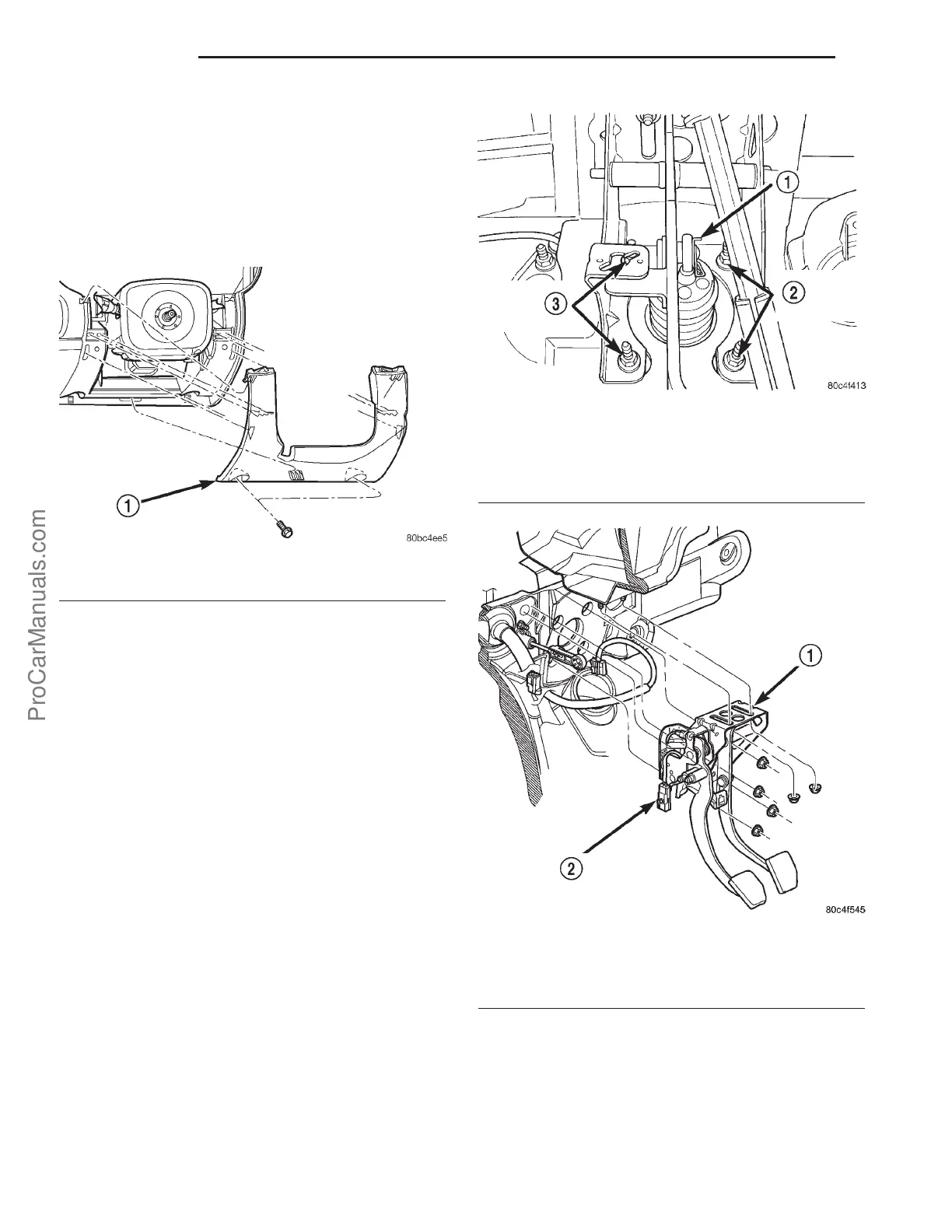
(2) Remove left lower instrument panel bezel (Fig.
4).
(3) Disconnect upstop switch and brake lamp
switch connectors.
(4) Disconnect clutch master cylinder rod from
clutch pedal pin. Inspect plastic retainer upon
removal. If retainer is damaged, it MUST be
replaced.
(5) Remove brake booster push rod retaining clip
from brake pedal. Disengage rod from pedal (Fig. 5).
(6) Remove two pedal assembly bracket to instru-
ment panel nuts (Fig. 6).
(7) Remove four brake booster/pedal bracket-to-
cowl panel nuts (Fig. 6).
(8) From under the hood, pull brake master cylin-
der/booster far enough forward to obtain pedal to
bracket stud clearance.
(9) Remove the pedal bracket assembly (Fig. 6).
(10) Remove pedal pivot shaft and remove brake
and clutch pedals.
(11) Remove the interlock/upstop switch assembly
(Fig. 7) from the brake/clutch pedal bracket assembly
by depressing the four plastic wing tabs on each
switch.
INSTALLATION
NOTE: Proper switch harness routing is critical to
switch durability. Note the harness routing and
location of fasteners intended to keep wires from
contacting pedals.
(1) Install switches into the pedal bracket assem-
bly as shown in (Fig. 7). Route harness as was prior
to removal.
(2) Install clutch and brake pedals to pedal
bracket, and install pivot shaft and nut. Torque pivot
shaft nut to 34 N·m (25 ft. lbs.).
Fig. 4 Steering Column Lower Cover
1 - LOWER COVER
Fig. 5 Brake Booster Mounting Nuts and Rod
Retaining Clip
1 - CLIP
2 - BOOSTER MOUNTING NUTS
3 - BOOSTER MOUNTING NUTS
Fig. 6 Brake/Clutch Pedal Assembly Removal/
Installation
1 - CLUTCH/BRAKE PEDAL ASSEMBLY
2 - INTERLOCK/UPSTOP SWITCH CONNECTOR
6s - 6 CLUTCH PL
ProCarManuals.com