sor and software contained within the Airbag Control
Module (ACM). The ACM also contains an impact
sensor and a safing sensor, which are monitored by
the ACM to determine when an impact occurs that is
severe enough to require front airbag system protec-
tion. When a frontal impact is severe enough, the
ACM initiates the inflator units of both front airbag
modules to deploy the airbags.
An airbag indicator lamp in the instrument cluster
lights for about six to eight seconds as a bulb test
each time the ignition switch is turned to the ON
position. Following the bulb test, the airbag indicator
lamp is turned ON or OFF by the ACM to indicate
the status of the airbag system. If the airbag indica-
tor lamp comes ON at any time other than during
the bulb test, it indicates that there is a problem in
the airbag system circuits. Such a problem may
cause the airbags not to deploy when required, or to
deploy when not required.
During a frontal vehicle impact, the knee blockers
work in concert with properly adjusted seat belts to
restrain the driver and front seat passenger in the
proper position for an airbag deployment. The knee
blockers also work to absorb and distribute the crash
energy from the driver and front seat passenger to
the structure of the instrument panel. The driver
side knee blocker is integral to the left lower instru-
ment panel bezel. The passenger side knee blocker is
integral to the glove box door.
Following are general descriptions of the major
components in the airbag system.
SIDE IMPACT AIRBAG SYSTEM
The side impact airbag control module (SIACM)
controls the seat back mounted airbags. If the
SIACM determines the impact is severe enough, the
appropriate airbag/s will inflate, tearing open the
front seat back trim cover/s protecting the passen-
ger/s. Once a seat back mounted airbag has been
deployed, all damaged parts must be replaced.
DIAGNOSIS AND TESTING - SIDE IMPACT
AIRBAG SYSTEM
Refer to the proper Body Diagnostic Procedures
manual.
STANDARD PROCEDURE - MAINTENANCE
INSPECTION
Check the airbag warning lamp for proper opera-
tion as follows:
(1) Turn the ignition switch to the ON position.
The airbag warning lamp should illuminate. If it
does not, test the system using a DRB lllt scan tool
and the proper Body Diagnostic Procedures manual.
Repair as required.
(2) If the airbag warning lamp lights but fails to
go out after ten seconds, test the system using a
DRB lllt scan tool and the proper Body Diagnostic
Procedures manual. Repair as required.
DRIVER AIRBAG
DESCRIPTION
The driver airbag protective trim cover is the most
visible part of the driver airbag system (Fig. 1). The
driver airbag is mounted directly to the steering
wheel. Located under the airbag trim cover are the
horn switch, the folded airbag cushion, and the air-
bag cushion supporting components. The resistive
membrane-type horn switch is secured within a plas-
tic tray between the driver airbag cover and the
backer plate which is heat staked on to the driver
airbag cover.
The driver airbag cannot be repaired, and must be
replaced if deployed or in any way damaged. The
driver airbag trim cover and the horn switch are
available for service replacement.
OPERATION
The driver airbag includes a stamped metal hous-
ing to which the cushion and an inflator unit are
attached and sealed. The conventional pyrotechnic-
type inflator assembly is mounted to studs on the
back of the airbag module housing. The inflator seals
the hole in the airbag cushion so it can discharge the
gas it produces directly into the cushion when sup-
plied with the proper electrical signal. Following an
airbag deployment, the airbag cushion quickly
deflates by venting this gas towards the instrument
panel through the porous fabric material used on the
steering wheel side of the airbag cushion.
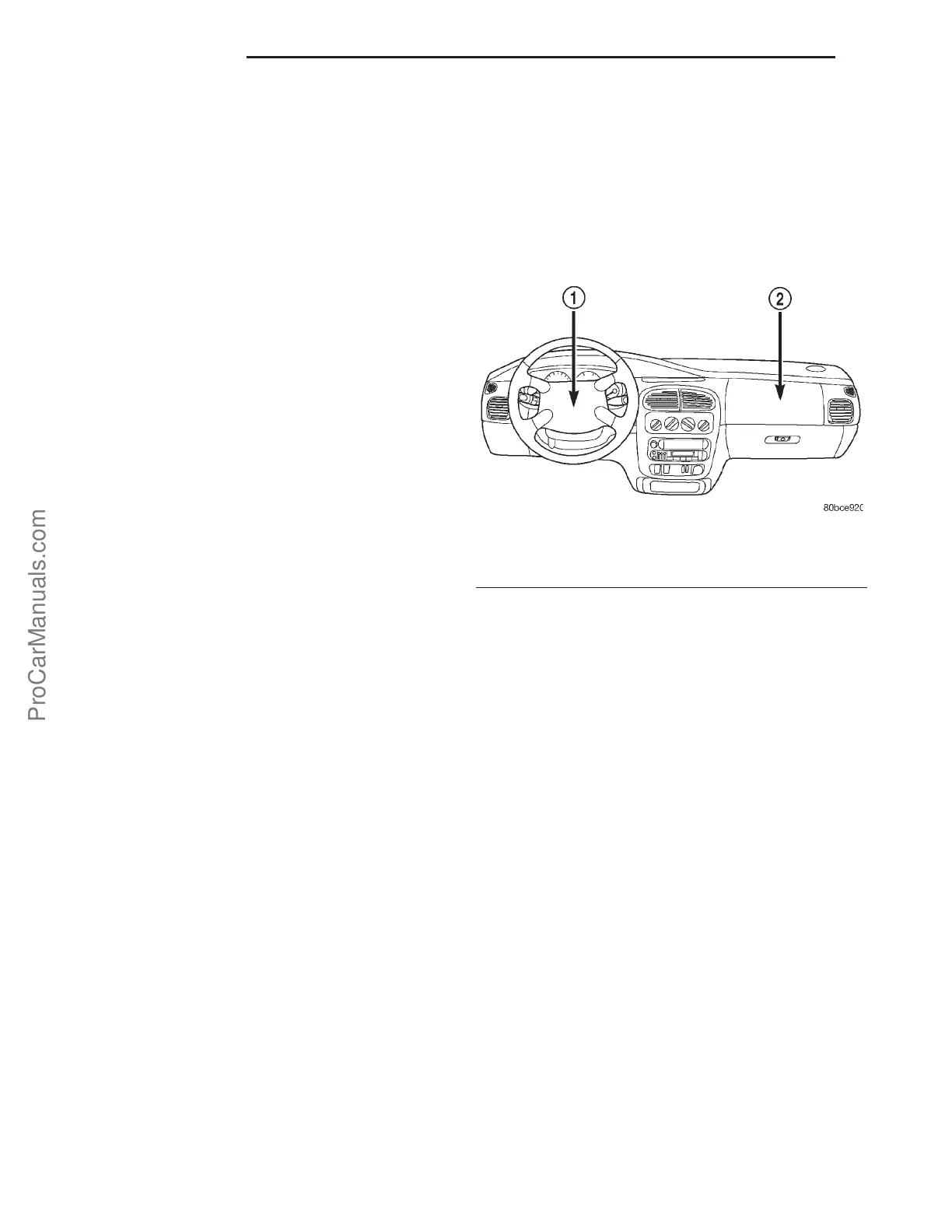
Fig. 1 DRIVER AIRBAG LOCATION
1 - DRIVER AIRBAG
2 - PASSENGER AIRBAG
8Os - 2 RESTRAINTS PL
8OS-RESTRAINTS-SUPPLEMENT (Continued)
ProCarManuals.com