(2) Install the brake pedal assembly onto the studs
extending down from the instrument panel support
and power brake booster (Fig. 11).
(3) Install the two nuts fastening the brake pedal
bracket to the instrument panel support (Fig. 11).
Install the nuts all the way, but do not tighten them
at this time.
(4) Install the power brake booster mounting nuts.
Tighten the four nuts fastening the brake pedal
bracket to the power brake booster to a torque of 34
N·m (300 in. lbs.).
(5) Tighten the two nuts fastening the brake pedal
bracket to the instrument panel support to a torque
of 34 N·m (300 in. lbs.).
(6) Connect the clutch cable to the clutch pedal
spacer on the pedal (Fig. 12).
(7) Connect the wiring harness connector going to
the clutch pedal switches (Fig. 13).
(8) Install the power brake booster input rod on
the pin mounted on the side of the brake pedal.
Install a new retaining clip on the end of the pin. Do
not reuse the old clip.
(9) Mount a new brake lamp switch into the
bracket. (Refer to 8 - ELECTRICAL/LAMPS/LIGHT-
ING - EXTERIOR/BRAKE LAMP SWITCH -
INSTALLATION)
(10) Install the instrument panel. (Refer to 23 -
BODY/INSTRUMENT PANEL/INSTRUMENT
PANEL ASSEMBLY - INSTALLATION).
(11) Check the stop lamps to verify they are oper-
ating properly and not staying on when the pedal is
in the released position.
(12) Road test the vehicle to ensure proper opera-
tion of the brakes.
POWER BRAKE BOOSTER-RHD
REMOVAL - RIGHT HAND DRIVE
(1) Disconnect and isolate the negative battery
cable.
CAUTION: Pump the brake pedal several times to
relieve the vacuum in the power brake booster. This
will prevent the booster from sucking in any con-
tamination when the master cylinder is removed.
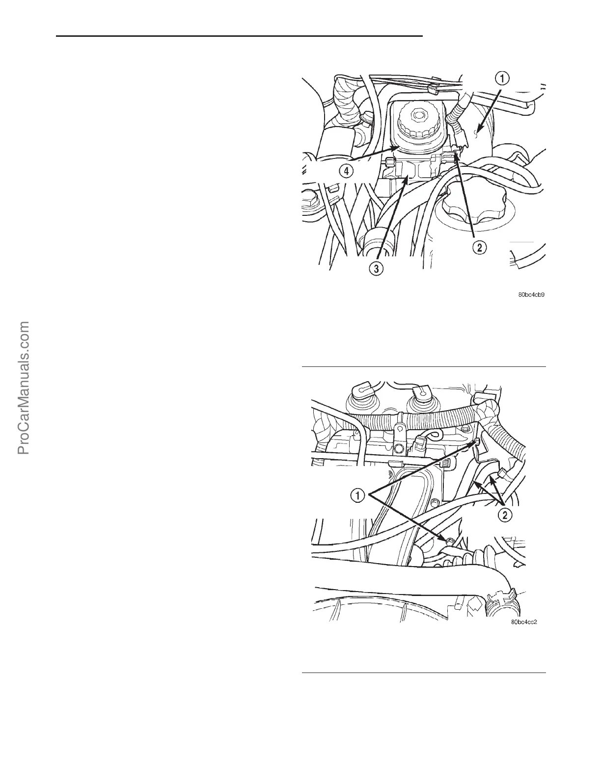
(2) Remove the master cylinder from the vehicle
(Fig. 14). (Refer to 5 - BRAKES/HYDRAULIC/ME-
CHANICAL/MASTER CYLINDER - REMOVAL).
(3) Remove the air cleaner assembly.
(4) Remove the battery and battery tray from the
vehicle. (Refer to 8 - ELECTRICAL/BATTERY SYS-
TEM/BATTERY - REMOVAL) (Refer to 8 - ELECTRI-
CAL/BATTERY SYSTEM/TRAY - REMOVAL).
(5) Remove the heater core coolant supply tube
support bracket bolts (Fig. 15).
(6) Remove the (2) coolant reservoir retaining bolts
from the dash panel. Disconnect the coolant overflow
hose from the thermostat housing and remove the
coolant reservoir from the dash panel.
Fig. 14 RHD MASTER CYLINDER
1 - POWER BRAKE VACUUM BOOSTER
2 - BRAKE FLUID LEVEL SENSOR
3 - MASTER CYLINDER
4 - BRAKE FLUID RESERVOIR
Fig. 15 HEATER CORE COOLANT SUPPLY HOSES
1 - COOLANT LINE SUPPORT BRACKET BOLTS
2 - HEATER CORE COOLANT SUPPLY LINES
PL BRAKES-BASE 5s - 15
PEDAL (Continued)
ProCarManuals.com