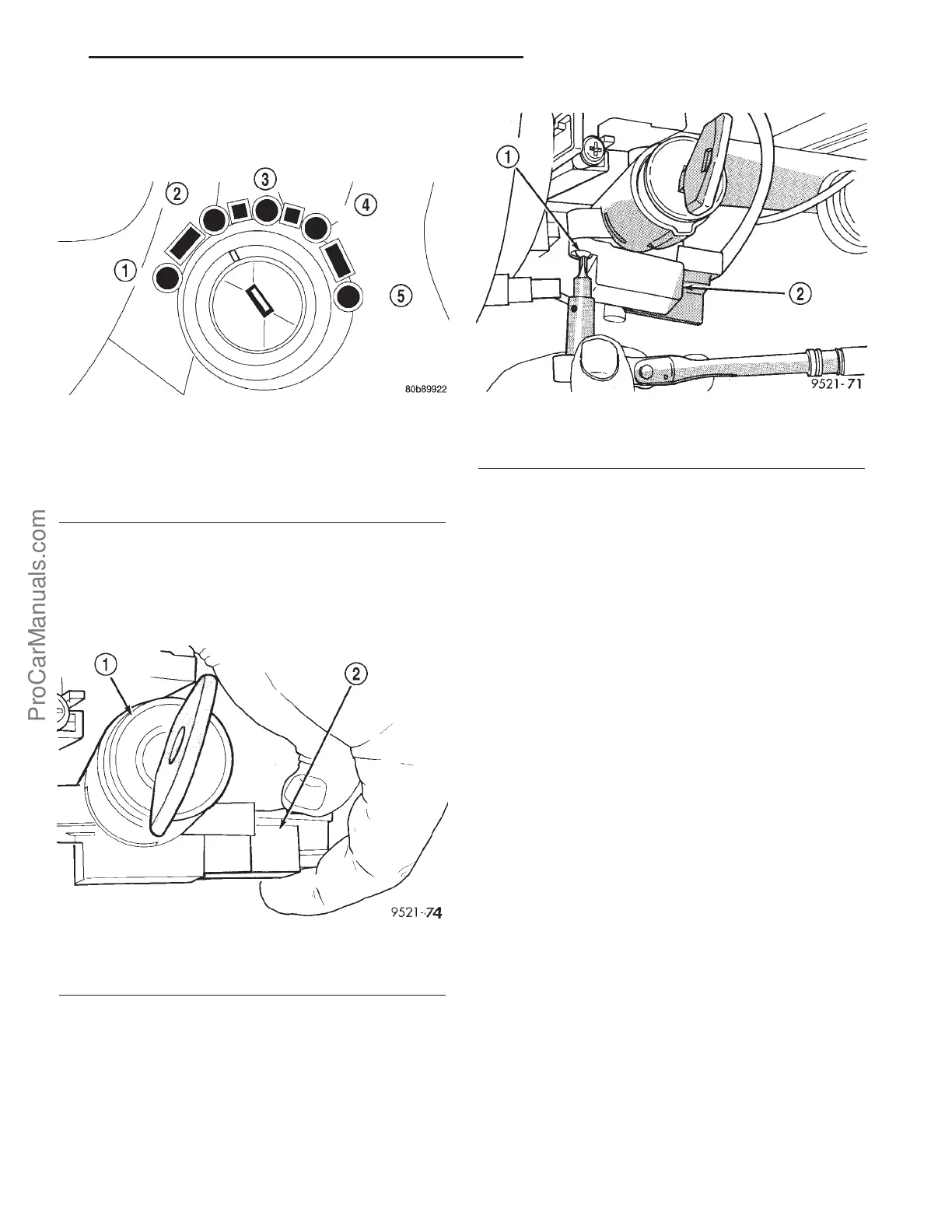
(3) Turn the ignition key to the “OFF” or “ON/
RUN” position (Fig. 279).
(4) Grasp the interlock cable and connector firmly.
Remove the interlock cable (Fig. 280).
(5) Remove the two interlock mechanism-to-steer-
ing column attaching screws (Fig. 281). Remove the
interlock housing.
INSTALLATION
(1) Position the interlock housing at steering col-
umn. Install the two interlock mechanism-to-steering
column attaching screws. Torque screws to 3 N·m (21
in. lbs.).
(2) Snap the interlock cable into the housing.
(3) Install steering column upper and lower
shrouds (Fig. 278).
(4) Install steering column lower cover (Fig. 277).
SHIFT INTERLOCK SYSTEM
DIAGNOSIS AND TESTING - BRAKE
TRANSMISSION SHIFT INTERLOCK
The following chart describes the normal operation
of the Brake Transmission Shift Interlock (BTSI) sys-
tem. If the “expected response” differs from the vehi-
cle’s response, then system repair and/or adjustment
is necessary. Refer to Brake Transmission Interlock
Removal and Installation or Adjustment in this
Group.
Fig. 279 Ignition Key/Switch Positions
1 - ACC
2 - LOCK
3 - OFF
4 - ON/RUN
5-START
Fig. 280 Interlock Cable
1 - IGNITION LOCK CYLINDER
2 - INTERLOCK CABLE
Fig. 281 Interlock Mechanism
1 - MOUNTING SCREW
2 - INTERLOCK MECHANISM
PL 41TE AUTOMATIC TRANSAXLE 21s - 177
SHIFT INTERLOCK MECHANISM (Continued)
ProCarManuals.com