POWER FOLDAWAY MIRROR
SWITCH
DESCRIPTION
Some vehicles are equipped with Power Fold-Away
Side View Mirrors. This feature allows both the
driver and passenger side view mirrors to fold
inward (retract) on demand. This feature is con-
trolled by a additional switch located on the power
mirror switch.
The fold-away side view mirror is attached to the
vehicle’s door in the same manner as mirrors without
the fold-away option. The fold-away mirrors unique
option is the internal motor which allows the mirrors
to fold inward on demand. The fold-away mirror
motor is not serviceable separately and if a motor is
found to be faulty the entire side view mirror must
be replaced.
OPERATION
When the mirror retract switch is depressed, both
of the side view mirrors will fold inward, Thus mak-
ing the overall width of the vehicle the smallest pos-
sible. This can be helpful were parking space is a
absolute minimum.
The power fold away mirror system consists of the
following components: mirror switch, side view mir-
ror, relay, wires and fuse. Refer to the appropriate
wiring information. The wiring information includes
wiring diagrams, proper wire and connector repair
procedures, details of wire harness routing and
retention, connector pin-out information and location
views for the various wire harness connectors, splices
and grounds.
DIAGNOSIS AND TESTING - POWER
FOLDAWAY MIRROR SWITCH
The following test is designed to be used only on
vehicles equipped with “retractable” or power fold-
away side view mirrors.
(1) Remove power mirror switch from mounting
position (Refer to 8 - ELECTRICAL/POWER MIR-
RORS/POWER FOLDAWAY MIRROR SWITCH -
REMOVAL).
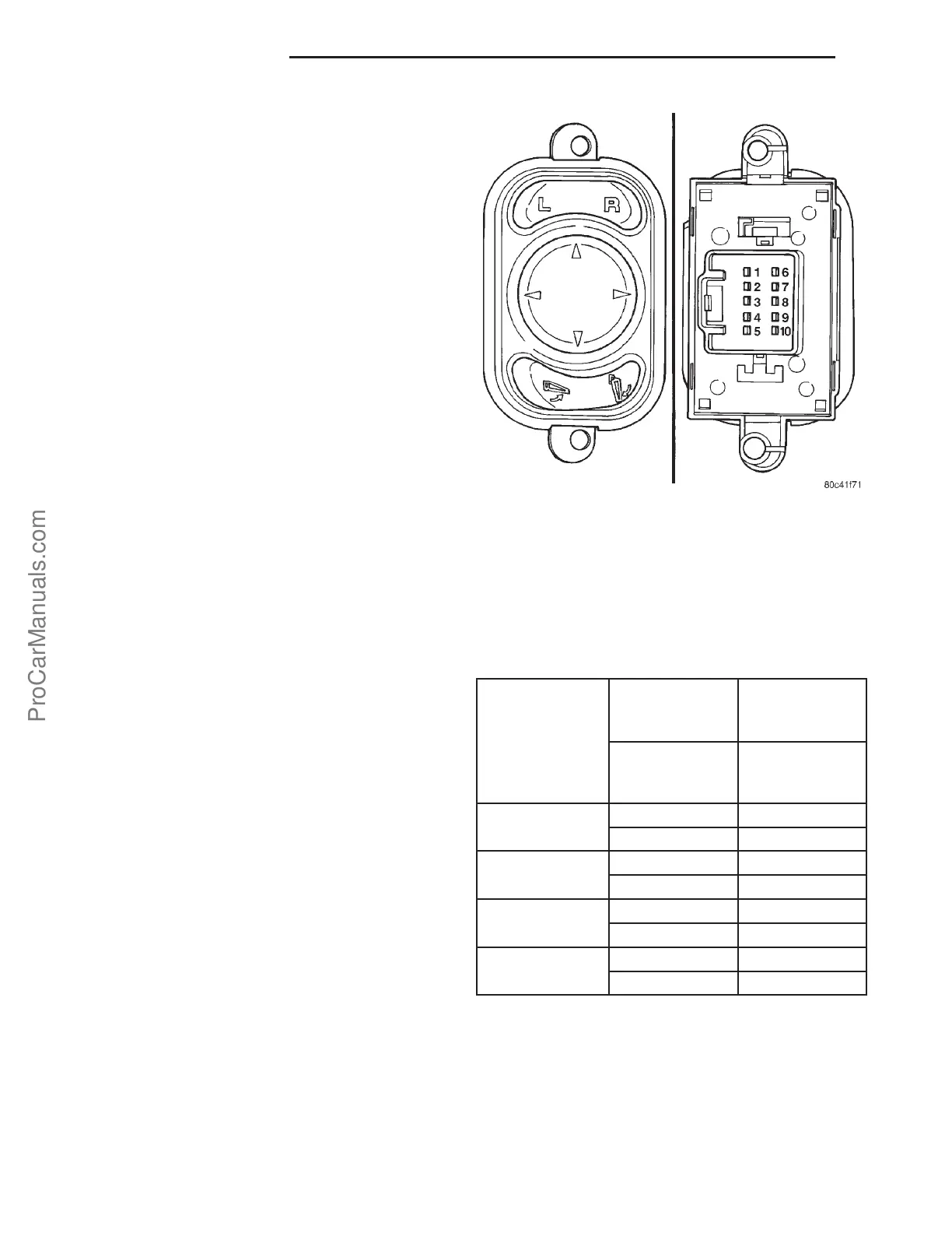
(2) Using an ohmmeter, test for continuity between
the terminals of the switch as shown in the tables
below.
NOTE: When testing using the chart below be cer-
tain to read the chart correctly. Example - When
testing left mirror “DOWN↓”, pins 1, 9, 10 will show
continuity to each other, and pins 3, 4, 5 will show
continuity to each other.
(3) If test results are not obtained as shown in the
tables below, replace the switch.
EXTENDED MIRROR SWITCH CIRCUIT TEST
NOTE: MIRROR POSITION SWITCH MUST BE IN
THE “UNFOLD” POSITION TO USE CHART BELOW.
WOBBLE
PLATE
POSITION
LEFT MIRROR
SELECTED
RIGHT
MIRROR
SELECTED
CONTINUITY
BETWEEN
PINS
CONTINUITY
BETWEEN
PINS
↓ 1-9-10 6-9-10
3-4-5 3-4-5
↑ 1-4-5 6-4-5
3-9-10 3-9-10
→ 2-9-10 7-9-10
3-4-5 3-4-5
2-4-5 7-4-5
3-9-10 3-9-10
Fig. 2 Power Fold-Away Mirror Switch
8Ns - 8 POWER MIRRORS PL
ProCarManuals.com