FRONT WHEEL SPEED
SENSOR
DESCRIPTION
The Mark 20e system uses two-wire wheel speed
sensors, known as active wheel speed sensors. The
sensors use an electronic principle known as magne-
toresistive to help increase performance and durabil-
ity. The sensors convert wheel speed into a small
digital signal. A wheel speed sensor is used at each
wheel. The gear (tooth) type tone wheel serves as the
trigger mechanism for each sensor. At each wheel of
the vehicle there is one wheel speed sensor and one
tone wheel.
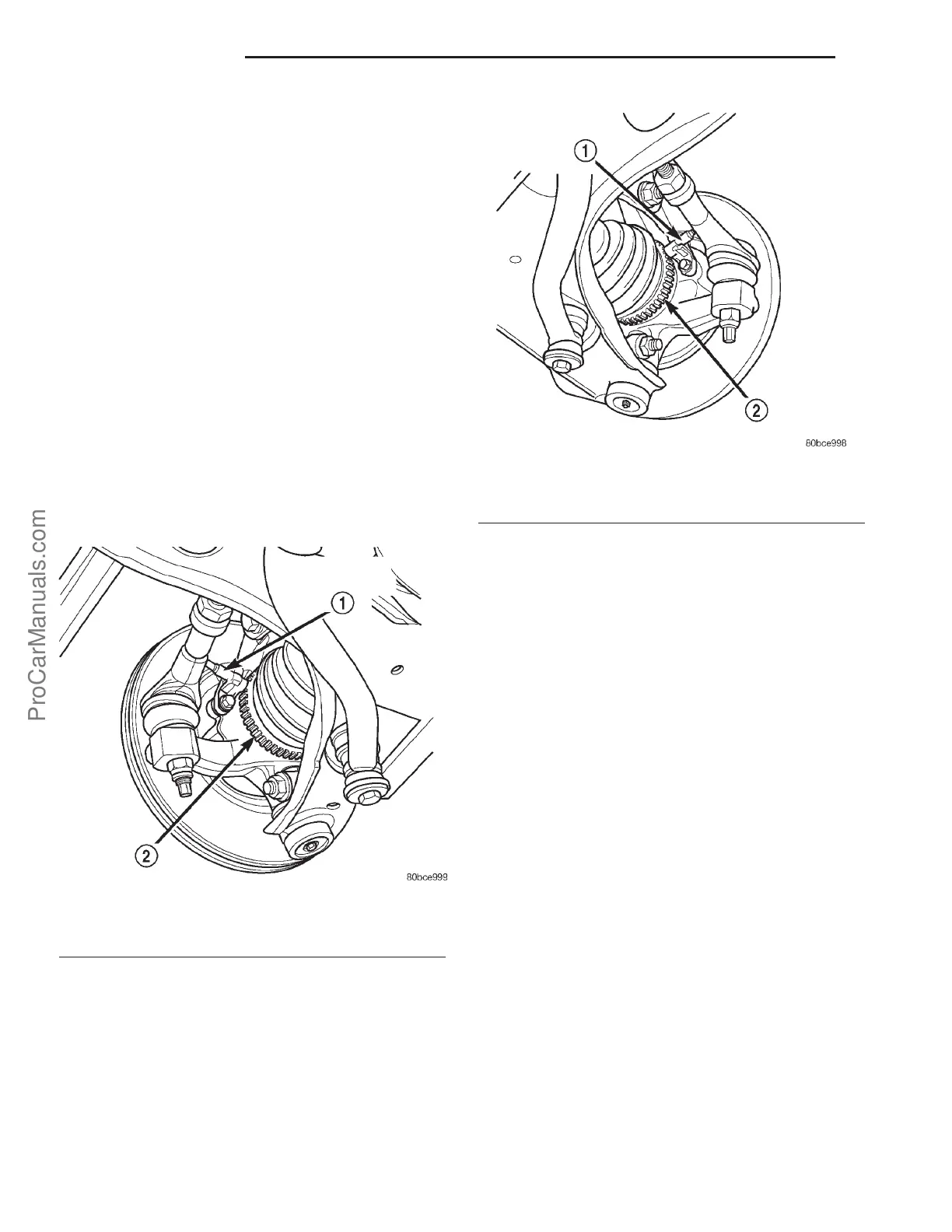
The front wheel speed sensors are attached to
bosses in the steering knuckle (Fig. 2) (Fig. 3). The
tone wheel is an integral part of the outboard con-
stant velocity joint located in the front axle shaft.
WSS air gaps are not adjustable. The initial fac-
tory WSS air gap specification can be found in SPEC-
IFICATIONS. Each WSS is serviced individually. The
tone wheels are serviced as part of the drive shaft.
OPERATION
The CAB sends 12 volts to power an Integrated
Circuit (IC) in the sensor. The IC supplies a constant
7 mA power supply to the CAB. The relationship of
the tooth on the tone wheel to the permanent magnet
in the sensor, signals the IC to enable a second 7 mA
power supply. The output of the sensor, sent to the
CAB, is a DC voltage signal with changing voltage
and current levels. The ground for the IC and the
current sense circuit is provided by the CAB.
When a valley of the tone wheel is aligned with the
sensor, the voltage signal is approximately 0.8 volts
and a constant 7 mA current is sent to the CAB. As
the tone wheel rotates, the tooth shifts the magnetic
field and the IC enables a second 7 mA current
source. The CAB senses a voltage signal of approxi-
mately 1.6 volts and 14 mA. The CAB measures the
amperage of the digital signal for each wheel. The
resulting signal is interpreted by the ABS CAB as
the wheel speed.
REAR WHEEL SPEED SENSOR
DESCRIPTION
The Mark 20e system uses two-wire wheel speed
sensors, known as active wheel speed sensors. The
sensors use an electronic principle known as magne-
toresistive to help increase performance and durabil-
ity. The sensors convert wheel speed into a small
digital signal. A wheel speed sensor is used at each
wheel. The gear (tooth) type tone wheel serves as the
trigger mechanism for each sensor. At each wheel of
the vehicle there is one wheel speed sensor and one
tone wheel.
The rear wheel speed sensors are mounted through
the disc brake adapter (Fig. 4) (Fig. 5). The rear tone
wheels are mounted to and rotate with the hub and
bearing assemblies.
The WSS air gaps are not adjustable. The initial
factory WSS air gap specification can be found in
Fig. 2 Left Front Wheel Speed Sensor
1 - LEFT FRONT WHEEL SPEED SENSOR
2 - TONE WHEEL
Fig. 3 Right Front Wheel Speed Sensor
1 - RIGHT FRONT WHEEL SPEED SENSOR
2 - TONE WHEEL
5s - 30 BRAKES-ABS PL
ProCarManuals.com