(10) Lock the clock spring rotor in the center posi-
tion as follows: Insert a paper clip wire through the
hole in the rotor at the 10 O’clock position and bend
to prevent it from falling out.
INSTALLATION
(1) Confirm that:
• The steering wheel position is a half turn (180
degrees) to the right (clockwise)
• The column is locked with the ignition cylinder
lock.
• Check that the turn signal stalk is in the neu-
tral position
• When reusing the clock spring, remove locking
wire and rotate clock spring rotor one half turn (180
degrees) to the right (clockwise). Locate the clock
spring on the steering shaft and push down on the
rotor until the clock spring is fully seated on the
steering column.
• When installing a new clock spring, position the
front wheels straight a head. Remove grenade pin.
Rotate clock spring rotor one half turn (180 degrees)
to the right (clockwise).
(2) Connect the clock spring to the instrument
panel harness, ensure wiring is properly routed.
Then check that the connectors, locking tabs are
properly engaged and the halo lamp wire is in posi-
tion.
(3) Install the multi-function switch. Refer to Elec-
trical, Lamps/Lighting - Exterior, Multi-Function
Switch, Installation.
(4) Install steering column shrouds. Be sure all
wires are inside of shrouds.
(5) Install steering wheel ensuring the flats on hub
align with the clock spring. Pull the horn, airbag and
speed control leads through the larger slot. Ensure
leads do not get pinched under the steering wheel.
(6) Route speed control wires under and behind
the airbag module mounting tabs.
(7) Connect the horn lead wire and the airbag lead
wire to the airbag module.
(8) Install the airbag module and tighten bolts to
12 to 14 N·m (105 to 125 in. lbs.) torque.
(9) Connect the speed control wires to the switches
and install switches. Tighten screws to 2 N·m (20 in.
lbs.) torque.
WARNING: DO NOT CONNECT THE BATTERY NEG-
ATIVE CABLE. REFER TO ELECTRICAL,
RESTRAINTS, DIAGNOSIS AND TESTING - AIRBAG
SYSTEM FIRST.
SEAT AIRBAG
DESCRIPTION
The left and right seat airbags (Fig. 13) are located
in the outboard edge of the front seat backs. The air-
bag contains a bag, an inflator (small canister of
highly compressed gas), and a mounting bracket. The
seat airbag cannot be repaired and must be replaced
if deployed or in any way damaged.
OPERATION
When supplied with the proper electrical signal,
the inflator seals the hole in the airbag cushion so it
can discharge the compressed gas directly into the
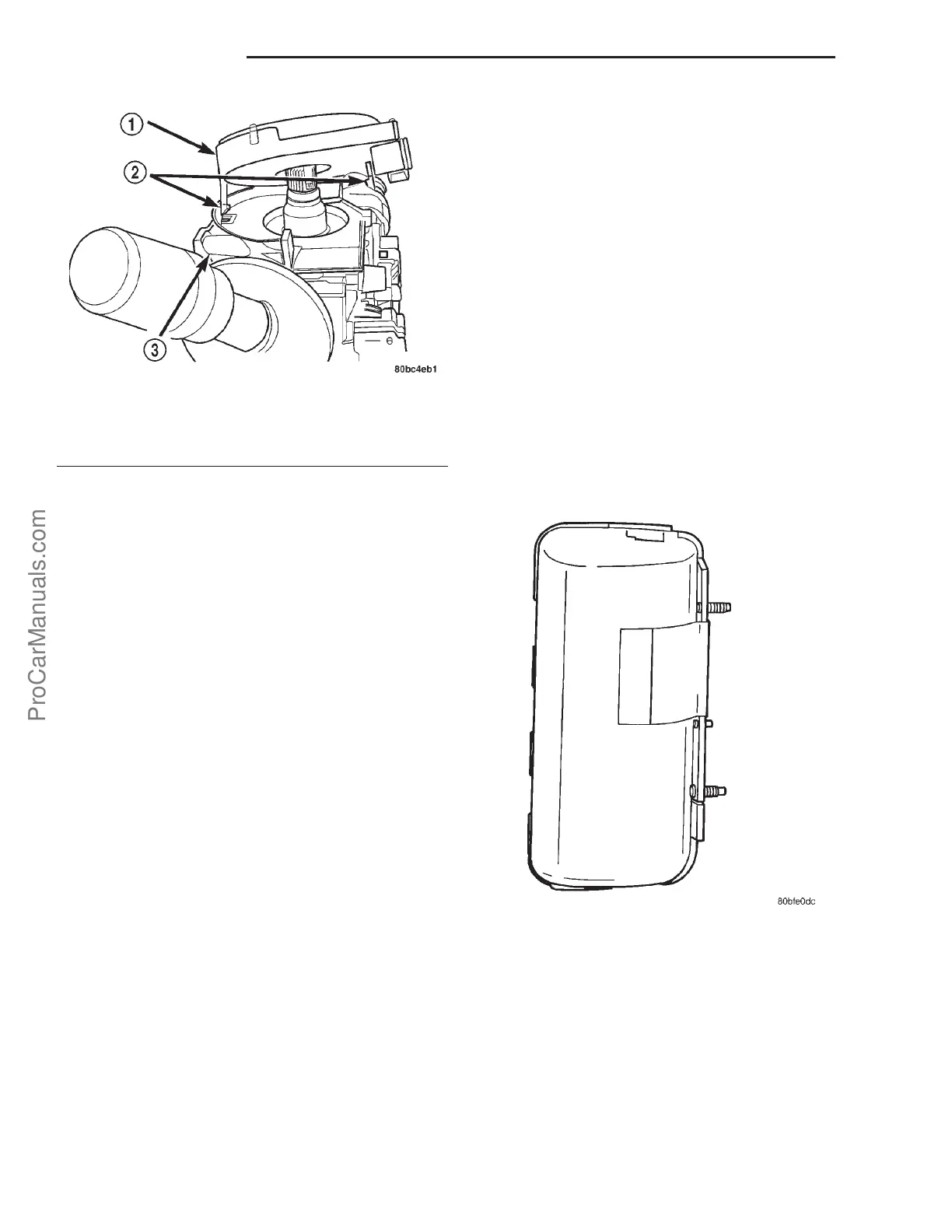
Fig. 12 CLOCK SPRING LATCH HOOKS
1 - CLOCK SPRING
2 - LATCH HOOKS
3 - STEERING COLUMN
Fig. 13 SEAT AIRBAG - TYPICAL
8Os - 8 RESTRAINTS PL
CLOCKSPRING (Continued)
ProCarManuals.com