INSTALLATION
CAUTION: Be certain the rubber 0-ring vacuum seal
is installed in the master cylinder mounting flange
prior to installation.
CAUTION: If a new master cylinder is being
installed, the cylinder must be bleed prior to instal-
lation.
(1) Slide the master cylinder assembly straight in
the power brake booster.
(2) Install the (2) master cylinder retaining nuts.
Torque the nuts to 28 N·m (250 in. lbs.).
(3) Install the brake lines on the master cylinder.
Torque the tube nuts to 17 N·m (145 in. lbs.).
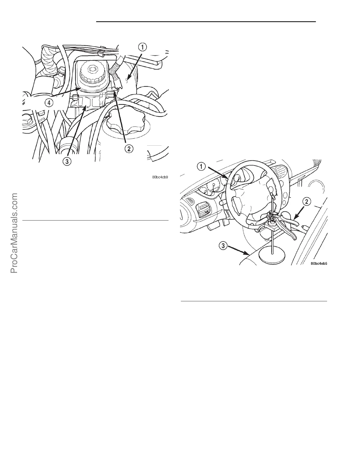
(4) Connect the brake fluid level sensor electrical
connector (Fig. 8).
(5) Fill the brake fluid reservoir to specification.
(6) Bleed the air from the hydraulic brake system.
WARNING: Be certain a firm brake pedal is
achieved prior to attempting to operate the vehicle.
PEDAL
REMOVAL
NOTE: Before proceeding with this procedure,
(Refer to 5 - BRAKES - WARNING).
WITH AUTOMATIC TRANSAXLE
(1) Disconnect and isolate the battery negative
cable from its post on the battery.
(2) Place the steering wheel and tires in the
STRAIGHT-AHEAD position. Using a steering wheel
holder, lock the steering wheel in place to keep it
from rotating (Fig. 9). This keeps the clockspring in
the proper orientation.
(3) Remove the steering column coupling retainer
pin, back off the pinch bolt nut, and remove the
steering column coupling pinch bolt (Fig. 10) (the
pinch bolt nut is caged to the coupling and is not
removable). Separate the upper and lower steering
column couplings.
(4) Remove the brake lamp switch. (Refer to 8 -
ELECTRICAL/LAMPS/LIGHTING - EXTERIOR/
BRAKE LAMP SWITCH - REMOVAL)
(5) Remove the clip securing the power brake
booster input rod to the brake pedal. Remove the
input rod from the brake pedal.
(6) Remove the two upper nuts fastening the brake
pedal bracket to the power brake booster (Fig. 11).
(7) Carefully pry the tie bar running between the
two upper booster mounting studs from its plastic
retaining fasteners.
Fig. 8 RHD MASTER CYLINDER
1 - POWER BRAKE VACUUM BOOSTER
2 - BRAKE FLUID LEVEL SENSOR
3 - MASTER CYLINDER
4 - BRAKE FLUID RESERVOIR
Fig. 9 Steering Wheel Holder
1 - STEERING WHEEL
2 - STEERING WHEEL HOLDER
3 - DRIVERS SEAT
5s - 12 BRAKES-BASE PL
MASTER CYLINDER-RHD (Continued)
ProCarManuals.com