(10) Raise vehicle on hoist.
(11) Remove converter heat shield (Fig. 45).
(12) Remove remaining grommet plate-to-floor pan
screw (Fig. 46).
(13) Remove cable assembly from vehicle.
INSTALLATION
NOTE: The crossover and selector cables are man-
ufactured as a cable “assembly” and cannot be ser-
viced individually.
CAUTION: Gearshift cable bushings must not be
lubricated or the bushings will swell and split.
(1) Raise vehicle on hoist.
(2) Install cable assembly through floor pan open-
ing and secure to floor pan with grommet plate and
one screw (Fig. 46). Make sure the three grommet
plate studs protrude through cable assembly and
floor pan and tighten screw to 7 N·m (60 in. lbs.).
(3) Route transaxle end of cable assembly into
engine compartment and over transaxle assembly.
(4) Install converter heat shield (Fig. 45).
(5) Lower vehicle.
(6) Install gearshift cables to mounting bracket
and fasten with NEW clips (Fig. 44). Make sure clips
are installed flush to bracket.
(7) Connect gearshift selector and crossover cable
to shift levers at transaxle (Fig. 44).
(8) Install and tighten the three grommet plate-to-
floor pan nuts to 6 N·m (50 in. lbs.) torque.
(9) Install selector cable to shifter lever and secure
cable to shifter bracket. Install clip (Fig. 42).
(10) Install crossover cable to shifter lever and
secure cable to shifter bracket. Install clip (Fig. 41).
NOTE: Only the crossover cable is adjustable. The
selector cable does not have any adjustment capa-
bilities.
(11) Adjust crossover cable as follows:
(a) Loosen adjusting screw on crossover cable at
shifter (Fig. 47).
(b) The gearshift mechanism and transaxle
crossover lever are spring-loaded and self-center-
ing. Alignment pins used in the past are not
required anymore. Allow gearshift mechanism and
transaxle crossover lever to relax in their neutral
positions. To ensure the gearshift lever is in the
proper position, place the shifter in 3rd or 4th gear
if necessary. Torque adjustment screw to 8 N·m (70
in. lbs.). Care must be taken to avoid moving the
shift mechanism off-center during screw tighten-
ing.
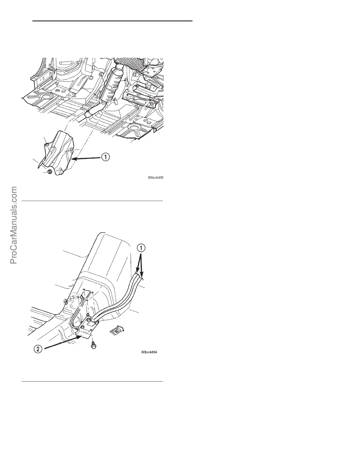
Fig. 45 Converter Heat Shield Removal/Installation
1 - CONVERTER HEAT SHIELD
Fig. 46 Shift Cable Assembly at Floor Pan
1 - CABLE ASSEMBLY
2 - GROMMET PLATE
PL A578 MANUAL TRANSMISSION 21s - 19
GEAR SHIFT CABLE (Continued)
ProCarManuals.com