(9) Remove engine oil dipstick from housing.
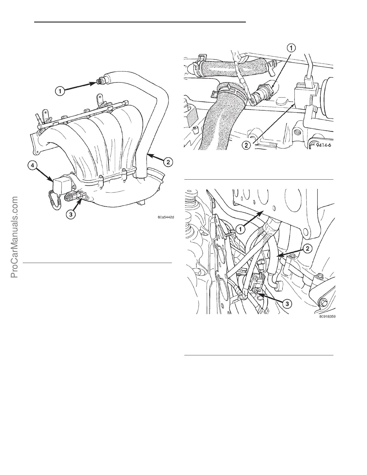
(10) Disconnect electrical connectors from MAP
sensor and MTV actuator (Fig. 5).
(11) Remove bolts attaching intake manifold to cyl-
inder head.
(12) Move manifold forward for access to wiring
connections (Fig. 7).
(13) Disconnect the knock sensor (Fig. 6).
(14) Disconnect brake booster hose (Fig. 7).
(15) Remove intake manifold.
INSTALLATION - HIGH OUTPUT ENGINE
(1) Clean manifold sealing surfaces.
(2) If separated, install lower to upper manifold
gasket and tighten bolt in sequence shown in (Fig. 8)
to 12 N·m (105 in. lbs.).
(3) Position new manifold gasket on cylinder head
mounting surface, piloting on the 2 attaching studs.
(4) Loosely position manifold in engine compart-
ment.
(5) Insert engine wiring harness between middle
intake runners.
(6) Connect the knock sensor (Fig. 6).
(7) Connect brake booster hose (Fig. 7).
(8) Position manifold to cylinder head and install
fasteners. Tighten fasteners in sequence shown in
(Fig. 9) to 12 N·m (105 in. lbs.).
Fig. 5 MAP, MTV & PCV Locations
1 - PCV VALVE (SCREWS INTO CYLINDER HEAD COVER)
2 - PCV HOSE (WITH INSULATED SLEEVE)
3 - MAP SENSOR
4 - MTV ACTUATOR
Fig. 6 Knock Sensor
1 - KNOCK SENSOR
2 - STARTER MOTOR
Fig. 7 Brake Booster Hose
1 - INTAKE MANIFOLD
2 - BRAKE BOOSTER HOSE
3 - STARTER WIRING
PL ENGINE-2.0L SOHC 9s - 3
INTAKE MANIFOLD-HIGH OUTPUT (Continued)
ProCarManuals.com














 To Next Page