(c) Verify throttle body duct is fully seated to
intake manifold and tighten clamp to 5 N·m (40 in.
lbs.) torque.
(d) Connect the Throttle Position Sensor (TPS)
and Idle Air Control (IAC) connectors.
(e) Connect proportional purge solenoid (PPS)
and crankcase vent hose from throttle body.
(13) Install center console assembly (Fig. 181).
(14) Install gearshift knob and tighten set screw to
2 N·m (15 in. lbs.) torque (Fig. 180).
(15) Connect battery cables.
(16) Verify that engine starter operates in both
PARK (P) and NEUTRAL (N). Starter should not
operate in any other gear position.
GEARSHIFT CABLE
Normal operation of the Park/Neutral Position
Switch provides a quick check to confirm proper link-
age adjustment. The engine starter should only oper-
ate when the transaxle shift lever is in the PARK (P)
or NEUTRAL (N) positions.
If the engine starts in any other gear position, or
the vehicle rolls when the shifter is in gated PARK
(P), a gearshift cable adjustment is necessary.
ADJUSTMENT
(1) Loosen set screw and remove knob from shifter
handle (Fig. 189).
(2) Remove the center console assembly as shown
in (Fig. 190).
(3) Adjust gearshift cable as follows:
(a) Place gearshift lever in the PARK (P) posi-
tion.
(b) Loosen shift cable adjustment screw (Fig.
191).
(c) Move transaxle manual lever to the PARK.
Verify transaxle is in PARK by attempting to roll
vehicle in either direction.
(d) Tighten shift cable adjustment screw to 8
N·m (70 in. lbs.) torque.
(4) Verify proper cable adjustment. Engine should
start with the shifter lever in PARK (P) and NEU-
TRAL (N) positions ONLY.
(5) Install center console assembly (Fig. 190).
(6) Install gearshift knob and tighten set screw to
2 N·m (15 in. lbs.) torque (Fig. 189).
HOLDING CLUTCHES
DESCRIPTION
Two hydraulically applied multi-disc clutches are
used to hold planetary geartrain components station-
ary while the input clutches drive others. The 2/4
and Low/Reverse clutches are considered holding
clutches and are contained at the rear of the trans-
axle case. (Fig. 192).
OPERATION
NOTE: Refer to the “Elements In Use” chart in Diag-
nosis and Testing for a collective view of which
clutch elements are applied at each position of the
selector lever.
Fig. 189 Gearshift Knob Removal/Installation
1 - SHIFTER KNOB
2 - SET SCREW
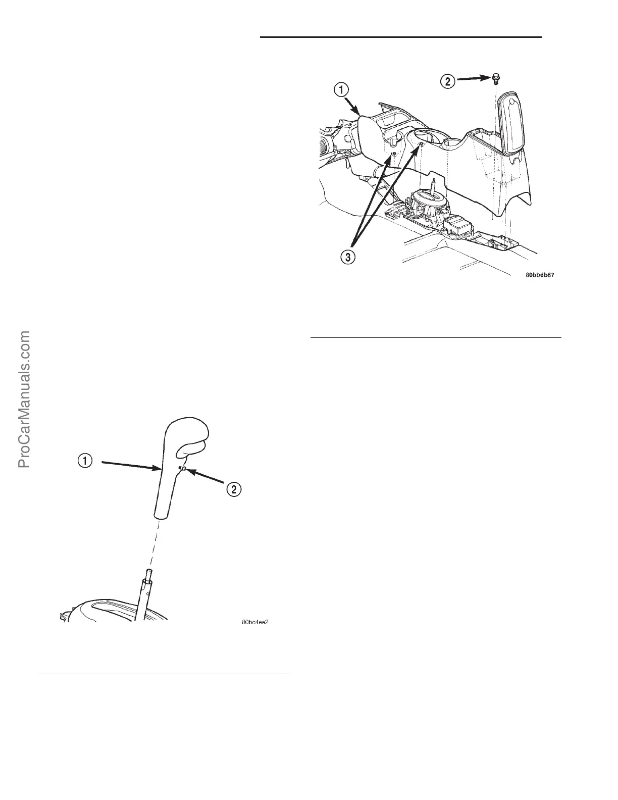
Fig. 190 Center Console Removal/Installation
1 - CONSOLE
2 - SCREW (4)
3 - SCREW (2)
21s - 152 41TE AUTOMATIC TRANSAXLE PL
GEARSHIFT CABLE (Continued)
ProCarManuals.com