(9) Rotate the ignition key to the “OFF” or “ON/
RUN” position (Fig. 274).
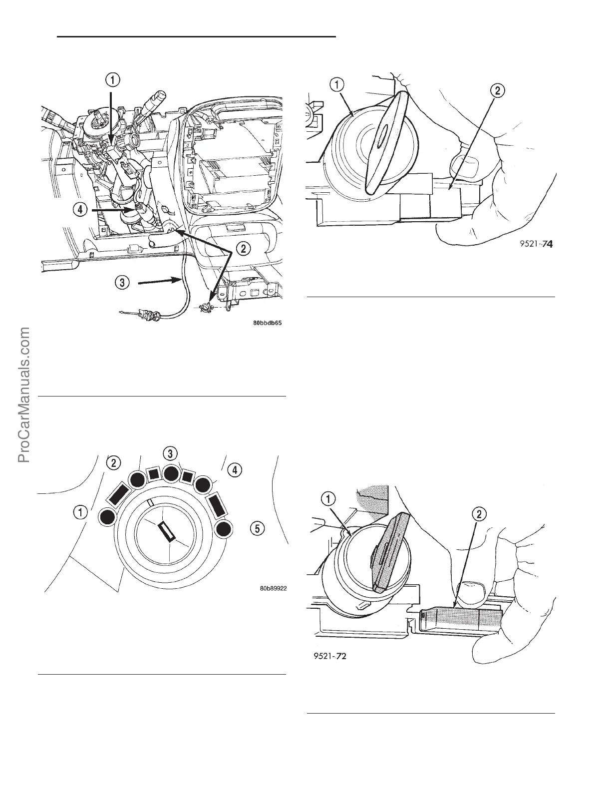
(10) Squeeze the interlock cable locking tab.
Remove the cable from the interlock housing (Fig.
275).
(11) Release cable from retaining clips and remove
through opening under steering column.
INSTALLATION
CAUTION: When installing interlock cable assembly,
care must be taken not to bend exposed cable wire
and slug at shifter end of cable.
(1) Route interlock cable through hole in instru-
ment panel below steering column and around to
gear shifter assembly.
(2) Turn the ignition key to the “OFF” or “ON/
RUN” position (Fig. 274).
(3) Install the interlock cable into the interlock
housing at the steering column (Fig. 276). Verify the
cable snaps into the housing and is fully seated.
Fig. 273 Interlock Cable at Steering Column
1 - IGNITION SWITCH
2 - CLIP
3 - INTERLOCK CABLE
4 - BTSI SOLENOID
Fig. 274 Ignition Key/Switch Positions
1 - ACC
2 - LOCK
3 - OFF
4 - ON/RUN
5-START
Fig. 275 Interlock
1 - IGNITION LOCK CYLINDER
2 - INTERLOCK CABLE
Fig. 276 Interlock Cable at Interlock Housing
1 - IGNITION SWITCH
2 - INTERLOCK CABLE
PL 41TE AUTOMATIC TRANSAXLE 21s - 175
SHIFT INTERLOCK CABLE (Continued)
ProCarManuals.com