(7) Remove solenoid/pressure switch assembly and
gasket (Fig. 288). Use care to prevent gasket mate-
rial and foreign objects from become lodged in the
transaxle case ports.
INSTALLATION
NOTE: If solenoid/pressure switch assembly is
being replaced, it is necessary to perform the TCM
Quick Learn Procedure. (Refer to 8 - ELECTRICAL/
ELECTRONIC CONTROL MODULES/TRANSMISSION
CONTROL MODULE - STANDARD PROCEDURE)
(1) Install solenoid/pressure switch assembly and
new gasket to transaxle (Fig. 288).
(2) Install and torque three (3) bolts (Fig. 287) to
13 N·m (110 in. lbs.).
(3) Install input speed sensor (Fig. 286) and torque
to 27 N·m (20 ft. lbs.).
(4) Connect input speed sensor connector.
(5) Install solenoid/pressure switch 8-way connec-
tor and torque to 4 N·m (35 in. lbs.).
(6) Install air cleaner/throttle body assembly.
(7) Connect battery negative cable.
(8) If solenoid/pressure switch assembly was
replaced, perform TCM Quick Learn procedure.
(Refer to 8 - ELECTRICAL/ELECTRONIC CON-
TROL MODULES/TRANSMISSION CONTROL
MODULE - STANDARD PROCEDURE)
SPEED SENSOR - INPUT
DESCRIPTION
The Input Speed Sensor is a two-wire magnetic
pickup device that generates AC signals as rotation
occurs. It is threaded into the transaxle case (Fig.
289), sealed with an o-ring (Fig. 290), and is consid-
ered a primary input to the Transmission Control
Module (TCM).
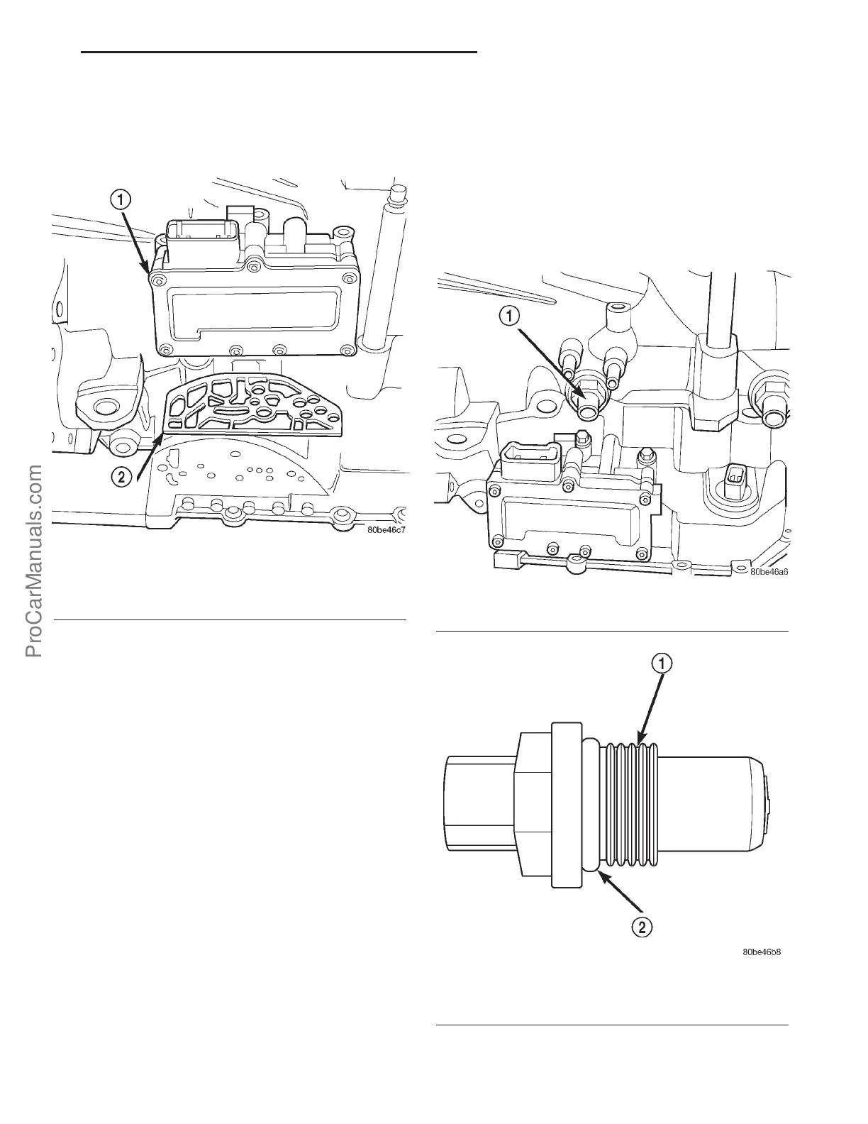
Fig. 288 Solenoid/Pressure Switch Assembly and
Gasket
1 - SOLENOID/PRESSURE SWITCH ASSEMBLY
2 - GASKET
Fig. 289 Input Speed Sensor Location
1 - INPUT SPEED SENSOR
Fig. 290 O-Ring Location
1 - INPUT SPEED SENSOR
2 - O-RING
PL 41TE AUTOMATIC TRANSAXLE 21s - 181
SOLENOID/PRESSURE SWITCH ASSY (Continued)
ProCarManuals.com