(3) Install brake/clutch pedal bracket assembly
into position. Install and tighten brake booster
mounting nuts to 34 N·m (25 ft. lbs.). Install and
tighten pedal bracket-to-instrument panel nuts to 34
N·m (25 ft. lbs.).
(4) Install new stop lamp switch.
(5) Connect brake booster rod to brake pedal.
Install retainer clip (Fig. 5).
CAUTION: Inspect clutch master cylinder pushrod
plastic retainer. If retainer is damaged in any way
(broken/cracked) it MUST be replaced.
(6) Connect clutch master cylinder pushrod.
Loosen adjustment screw (Fig. 8) and gently lift
clutch pedal upwards until the clutch pedal fully
depresses the the upstop switch. Torque adjustment
screw to 8 N·m (70 in. lbs.).
(7) Connect interlock/upstop and stop lamp switch
connectors.
(8) Install left lower instrument panel bezel (Fig.
4).
(9) Connect battery negative cable.
(10) Verify proper switch operation.
RELEASE BEARING AND FORK
DESCRIPTION
A conventional release bearing is used to engage
and disengage the clutch pressure plate. The clutch
release bearing is mounted on the transaxle front
bearing retainer. The bearing is attached to and oper-
ated by the release fork (Fig. 9), which moves the
bearing into contact with the clutch cover diaphragm
spring.
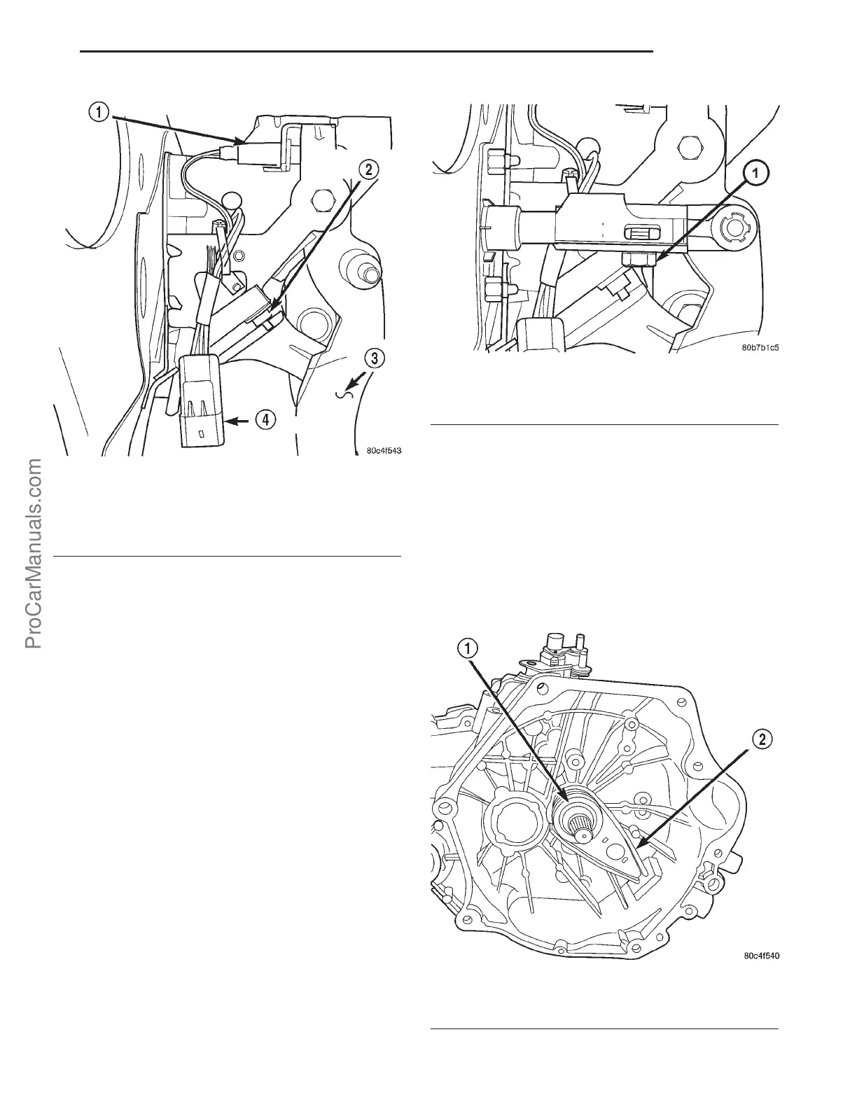
Fig. 7 Interlock/Upstop Switch
1 - UPSTOP SWITCH
2 - INTERLOCK SWITCH
3 - CLUTCH PEDAL
4 - CONNECTOR
Fig. 8 Clutch Master Cylinder Pushrod Adjustment
Screw
1 - ADJUSTMENT SCREW
Fig. 9 Clutch Release Bearing and Fork
1 - RELEASE BEARING
2 - PIVOT FORK
PL CLUTCH 6s - 7
CLUTCH INTERLOCK UPSTOP SWITCH (Continued)
ProCarManuals.com