(6) Remove the four nuts fastening the brake pedal
bracket to the power brake booster (Fig. 11).
(7) Remove the two nuts fastening the brake pedal
bracket to the instrument panel support (Fig. 11).
(8) Remove the brake pedal assembly.
(9) The pedal can be removed from it’s bracket by
grinding off the peened end of the shaft, removing
the shaft, pedal and bushings. A service parts pack-
age is available to replace these items.
INSTALLATION
NOTE: Before proceeding with this procedure,
(Refer to 5 - BRAKES - WARNING).
WITH AUTOMATIC TRANSAXLE
(1) If the pedal has been removed from it’s
bracket, install the pedal, bushings and bolt-in-shaft
on the bracket using the available service parts pack-
age.
(2) Install the brake pedal assembly by tipping the
pedal bracket and guiding the power brake booster
mounting portion up past the booster input rod.
Guide the top of the bracket onto the studs protrud-
ing from the instrument panel support (Fig. 11), then
guide the booster mounting portion onto the power
brake booster mounting studs.
(3) Push the power brake booster back into mount-
ing position from under the hood.
(4) Install the two nuts fastening the brake pedal
bracket to the instrument panel support (Fig. 11).
Install the nuts all the way, but do not tighten them
at this time.
(5) Install the two lower power brake booster
mounting nuts, but do not tighten them at this time.
(6) Place the tie bar running between the two
upper booster mounting studs onto the studs with
the long flat side facing upward and the curved side
downward.
(7) Install the two upper power brake booster
mounting nuts on their studs.
(8) Tighten all four nuts fastening the brake pedal
bracket to the power brake booster to a torque of 34
N·m (300 in. lbs.).
(9) Tighten the two nuts fastening the brake pedal
bracket to the instrument panel support to a torque
of 34 N·m (300 in. lbs.).
(10) Install the power brake booster input rod on
the pin mounted on the side of the brake pedal.
Install a new retaining clip on the end of the pin. Do
not reuse the old clip.
(11) Mount a new brake lamp switch into the
bracket (Refer to 8 - ELECTRICAL/LAMPS/LIGHT-
ING - EXTERIOR/BRAKE LAMP SWITCH -
INSTALLATION).
(12) Install the dash-to-lower coupling seal in
place over the lower coupling’s plastic collar and
dash cover.
(13) Verify the front tires are still in the
STRAIGHT-AHEAD position.
(14) Reconnect the steering column lower coupling
to the steering column upper coupling (Fig. 10).
Install the coupling pinch bolt an tighten the pinch
bolt nut to a torque of 28 N·m (250 in. lbs.). Install
the pinch bolt retainer pin.
(15) Remove the steering wheel holder (Fig. 9).
(16) While looking under the instrument panel at
the lower coupling, rotate the steering wheel back-
and-forth to verify that the lower coupling does not
squeak against the dash-to-coupling seal.
(17) Reconnect the battery negative terminal.
(18) Check the stop lamps to verify they are oper-
ating properly and not staying on when the pedal is
in the released position.
(19) Road test the vehicle to ensure proper opera-
tion of the brakes.
WITH MANUAL TRANSAXLE
(1) If the pedal has been removed from it’s
bracket, install the pedal, bushings and bolt-in-shaft
on the bracket using the available service parts pack-
age.
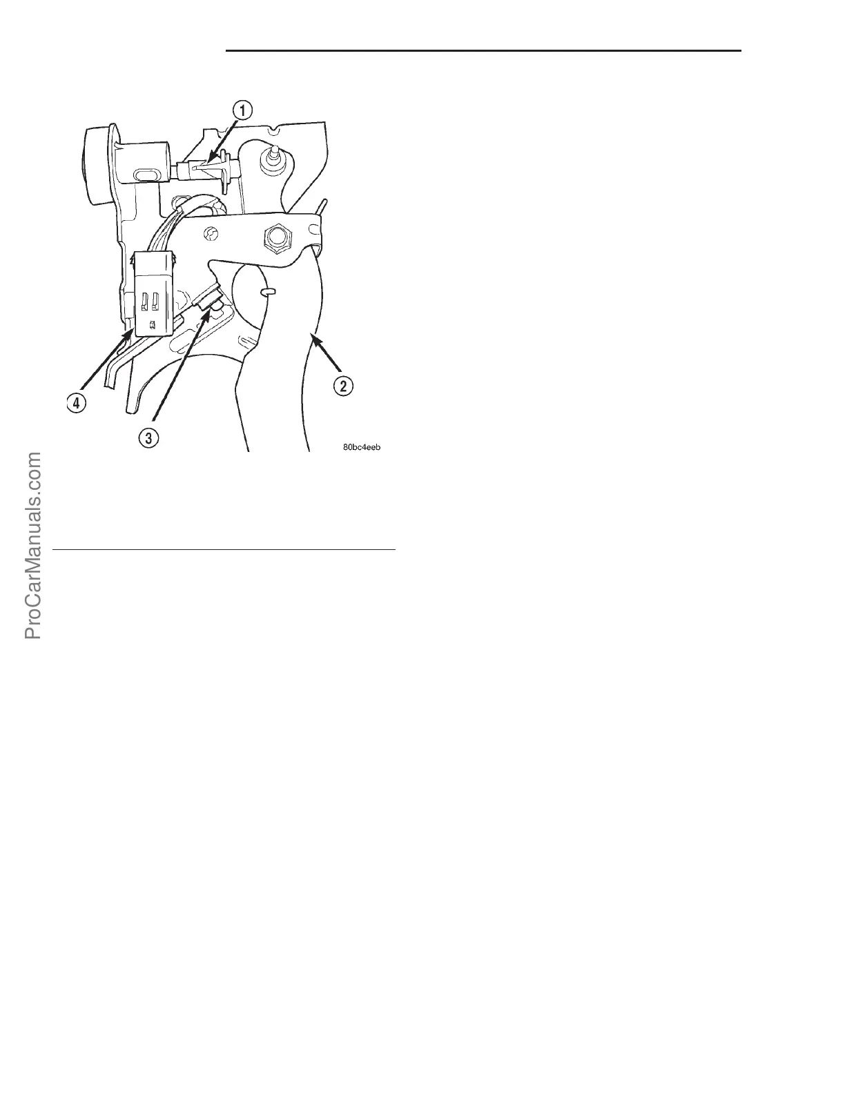
Fig. 13 Wiring Harness Connector
1 - UPSTOP SWITCH
2 - CLUTCH PEDAL
3 - INTERLOCK SWITCH
4 - CONNECTOR
5s - 14 BRAKES-BASE PL
PEDAL (Continued)
ProCarManuals.com