(9) With the aid of a helper, apply pressure to the
brake pedal until the reading on proportioning valve
inlet gauge is at the target inlet pressure shown in
the BRAKE PROPORTIONING VALVE APPLICA-
TIONS AND PRESSURE SPECIFICATIONS table
following this procedure. If the inlet gauge pressure
overshoots its target pressure when the pedal is
depressed, release the brake pedal, relieving the
pressure in the system, before reapplying the pedal
to reach the target pressure at the inlet gauge. This
is necessary to get an accurate reading of the outlet
pressure.
(10) Once inlet pressure has been achieved, check
the pressure reading on the proportioning valve out-
let gauge. If the proportioning valve outlet pressure
does not agree with value shown in the table, replace
the proportioning valve. If proportioning valve is
within pressure specifications, the valve is good and
does not require replacement.
(11) Reinstall the brake holding tool on the brake
pedal and remove the test equipment from the vehi-
cle.
(12) Remove the tools from the proportioning
valve.
(13) Install the proportioning valve in the master
cylinder and hand tighten until the proportioning
valve is fully installed and its O-ring seal is seated
into the master cylinder. Torque the proportioning
valve to 17.5 N·m (155 in. lbs.).
(14) Install the brake tube on the proportioning
valve. Torque the tube nut to 17 N·m (145 in. lbs.).
(15) Bleed the affected brake line. (Refer to 5 -
BRAKES - STANDARD PROCEDURE).
BRAKE PROPORTIONING VALVE APPLICATIONS AND PRESSURE SPECIFICATIONS
Sales
Code
Brake System Type Split Point Slope Identification
Inlet
Pressure
Outlet Pressure
BRA 149 Disc/Drum 300 psi 0.34 Red Band 1000 psi 480-580 psi
BRD 149 Disc/Disc 350 psi 0.34 Purple Band 1000 psi 525-625 psi
BRX 149 Disc/Disc 350 psi 0.34 Purple Band 1000 psi 525-625 psi
REMOVAL
NOTE: Before proceeding with this procedure,
(Refer to 5 - BRAKES - WARNING).
(1) Using a brake pedal holder, depress the brake
pedal past its first one inch of travel and hold it in
this position (Fig. 20). This will isolate the master
cylinder from the brake hydraulic system and will
not allow the brake fluid to drain out of the master
cylinder reservoir.
(2) Disconnect the brake tube from the proportion-
ing valve requiring removal (Fig. 21).
(3) Unscrew the Proportioning valve from the mas-
ter cylinder.
INSTALLATION
NOTE: Before proceeding with this procedure,
(Refer to 5 - BRAKES - WARNING).
(1) Lubricate the O-ring on the proportioning
valve. Make sure the O-ring on the proportioning
valve is new.
(2) Install the proportioning valve in its master
cylinder port. Tighten the proportioning valve to a
torque of 17.5 N·m (155 in. lbs.).
(3) Connect the brake tube to the proportioning
valve (Fig. 21). Tighten the tube nut to a torque of 17
N·m (145 in. lbs.).
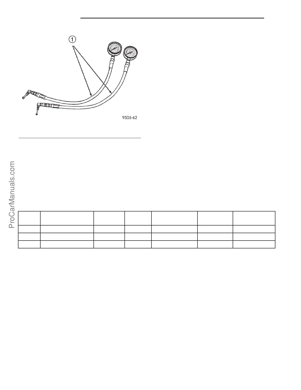
Fig. 19 Pressure Gauge Set
1 - SPECIAL TOOL C-4007–A
5s - 18 BRAKES-BASE PL
PROPORTIONING VALVE (Continued)
ProCarManuals.com