NOTE: The use of two drift pins or 1/2 inch diame-
ter bolts through the B-pillar pilot holes will assure
proper vertical position of the panel. Otherwise,
visual align these holes before tightening the first
bolt on each side.
(3) Connect the center console wiring:
• Airbag Control Module (ACM)
• Parking Brake Warning Lamp Switch
• Transmission Range Indicator Lamp
• Brake Interlock Cable (ATX)
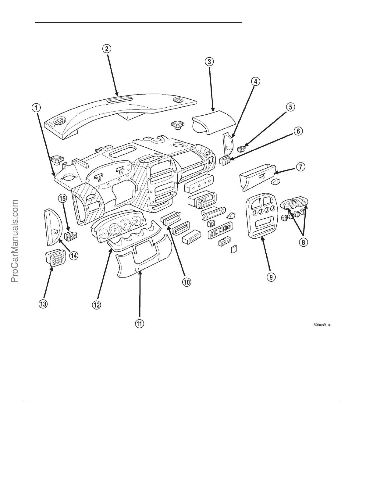
Fig. 4 INSTRUMENT PANEL ASSEMBLY
1 - INSTRUMENT PANEL ASSEMBLY 9 - BEZEL INSTRUMENT PANEL, CENTER
2 - UPPER COVER INSTRUMENT PANEL 10 - BIN, LOWER STORAGE
3 - MODULE, PASSENGER SIDE AIRBAG 11 - COVER, LOWER INSTRUMENT PANEL
4 - END CAP, RIGHT 12 - CLUSTER BEZEL
5 - DEMISTER GRILLE, RIGHT 13 - LOUVER, AIR OUTLET, LEFT
6 - LOUVER, AIR OUTLET, RIGHT 14 - END CAP, LEFT
7 - DOOR, GLOVE BOX 15 - DEMISTER GRILLE, LEFT
8 - LOUVER, AIR OUTLET, CENTER
PL INSTRUMENT PANEL 23s - 9
INSTRUMENT PANEL ASSEMBLY (Continued)
ProCarManuals.com