EasyManuals Logo

ELTEX ESR Series User Manual

ELTEX ESR Series
575 pages
To Next Page IconTo Next Page
To Previous Page IconTo Previous Page
Page #44 background imageLoading...
Page #44 background image
ESR-Series. User manual
44
Front
panel
element
Description
Alarm Alarm LED.
VPN Active VPN sessions indicator.
Flash Activity indicator of exchange with data storages (SD-card or USB Flash).
Power Device power LED.
Master Indicator of failover modes operation.
Fan Fan operation LED.
RPS Redundant power supply LED.
7 F Functional key that reboots the device and resets it to factory default configuration:
Pressing the key for less than 10 seconds reboots the device;
Pressing the key for more than 10 seconds resets the terminal to factory settings.
8 Console Console port RS-232 for local management of the device.
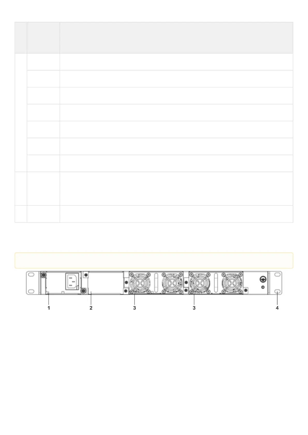
ESR-1200, 1000 rear panel
The rear panel of ESR-1000 is depicted in the figure below.
Figure 16 – ESR-1000 rear panel
Table 18 lists rear panel connectors of the router.
The figure shows the router delivery package with a single AC power supply.

Table of Contents

Questions and Answers:

Question and Answer IconNeed help?

Do you have a question about the ELTEX ESR Series and is the answer not in the manual?

ELTEX ESR Series Specifications

General IconGeneral
ModelESR Series
CategoryNetwork Router
ManufacturerELTEX
ManagementWeb interface, CLI, SNMP
Operating Temperature0°C to 40°C
DimensionsVaries by model
WeightVaries by model
Routing ProtocolsOSPF, BGP
WAN InterfacesEthernet, SFP
LAN InterfacesEthernet, SFP
VPN SupportIPsec, L2TP, PPTP
FirewallStateful packet inspection, ACLs
Power over Ethernet (PoE)Available on some models
QoSTraffic prioritization

Related product manuals