•
•
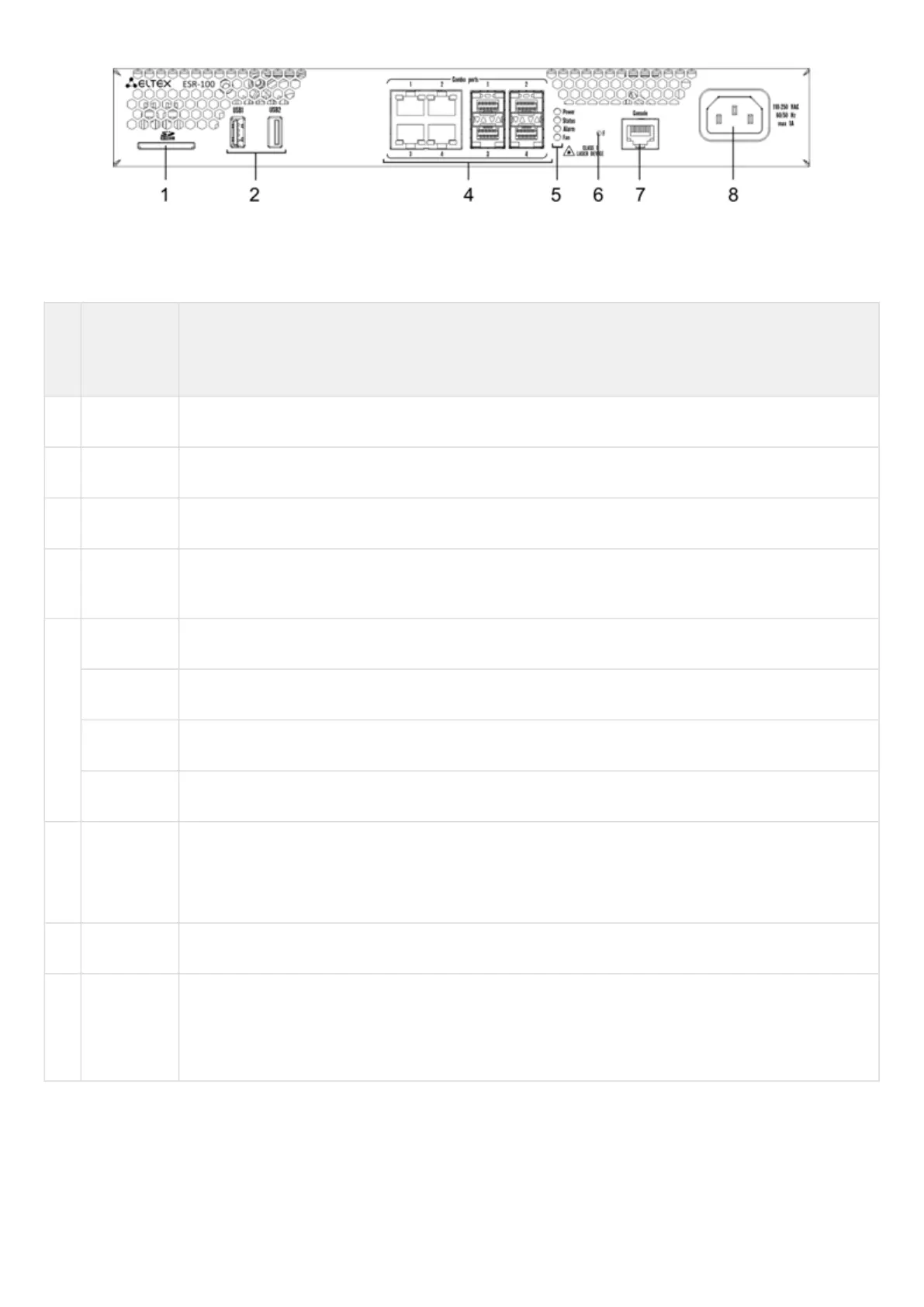
Figure 20 – ESR-100 front panel
Table 19 lists connectors, LEDs and controls located on the front panel of ESR-100 and ESR-200 routers.
Table 19 – Description of connectors, LEDs and controls located on ESR-200, ESR-100 front panel
№ Front
panel
element
Description
1 SD SD-card connector.
2 USB1, USB2 2 x USB-enabled devices connection port.
3 [1 .. 4] 4 ports of Gigabit Ethernet 10/100/1000BASE-T (RJ-45).
4 Combo
Ports
4 ports of Gigabit Ethernet 10/100/1000BASE-X (SFP).
5 Power Device power LED.
Status Current device status LED.
Alarm Alarm LED.
Fan Fan operation LED.
6 F Functional key that reboots the device and resets it to factory default configuration:
Pressing the key for less than 10 seconds reboots the device;
Pressing the key for more than 10 seconds resets the terminal to factory settings.
7 Console Console port RS-232 for local management of the device.
8 110-250
VAC
60/50 Hz
max 1A
Power supply.
ESR-200, ESR-100 rear panel
The rear panel layout of ESR-200 and ESR-100 routers is depicted in figure 21.

 Loading...
