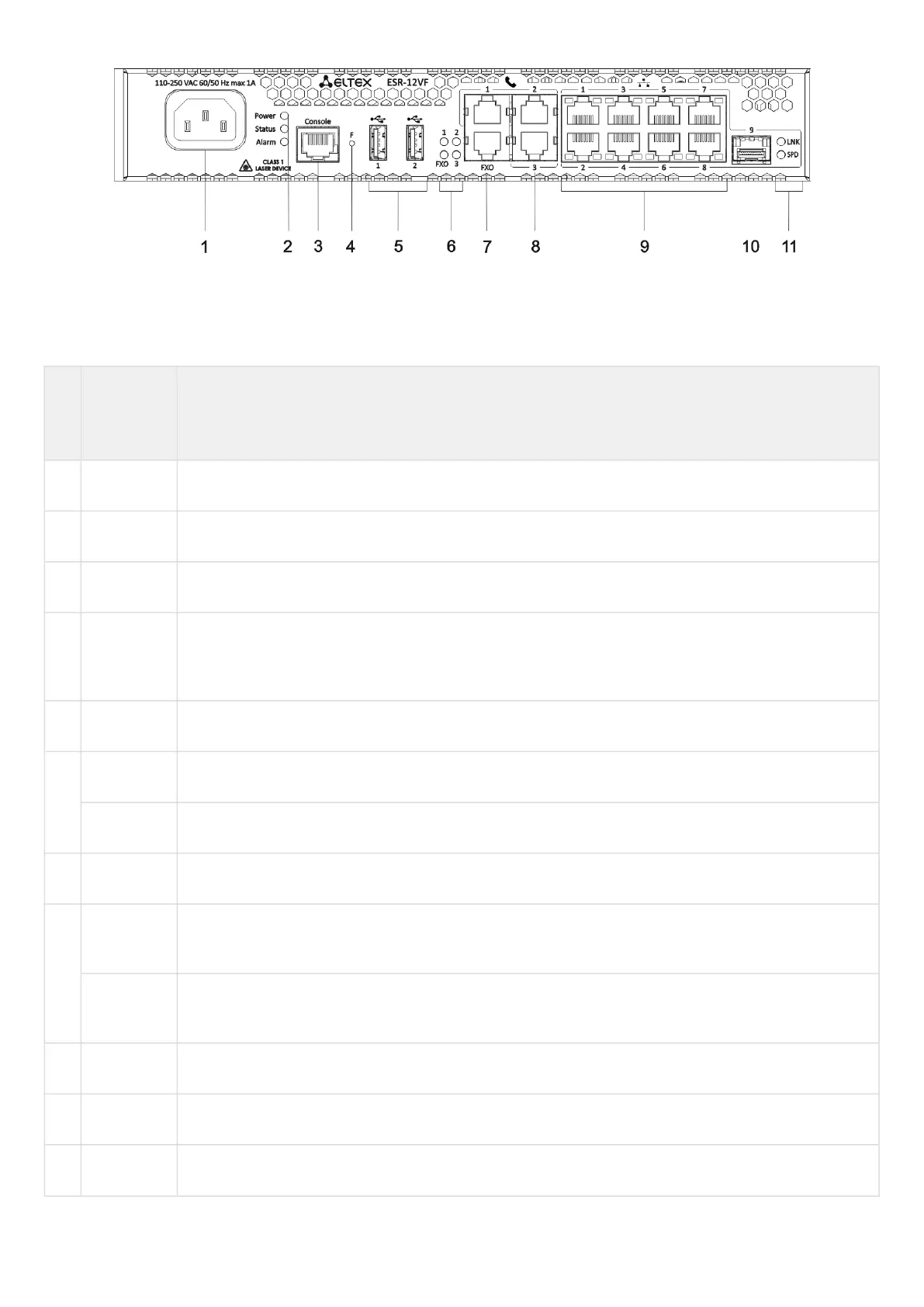
Figure 32 – ESR-12VF, ESR-14VF front panel
Table 25 lists connectors, LEDs and controls located on the front panel of ESR-12VF and ESR-14VF routers.
Table 25 – Description of connectors, LEDs and controls located on ESR-12VF, ESR-14VF front panel
№ Front
panel
element
Description
1 220V АC Power supply.
2 Power Device power LED.
3 Console Console port RS-232 for local management of the device.
4 F Functional key that reboots the device and resets it to factory default configuration: - pressing the
key for less than 10 seconds reboots the device. - pressing the key for more than 10 seconds resets
the device to factory default configuration.
5 USB1, USB2 2 USB connectors for connecting external USB devices.
6 FXO PSTN external subscriber line LED.
1,2,3 Internal subscriber terminals LED.
7 FXO 1 FXO connector for connection PSTN external subscriber line (only for ESR-12VF).
8 FXS 1, FXS
2, FXS 3
3 connectors for internal subscriber terminals (for ESR-12VF).
FXS 1, FXS
2, FXS 3
4 connectors for internal subscriber terminals (for ESR-14VF).
9 [1 .. 8] 8 ports of Gigabit Ethernet 10/100/1000BASE-T (RJ-45).
10 Optical Port 1 port of Gigabit Ethernet-100/1000BASE-X (SFP)
11 1,2 Optical interfaces LED

 Loading...
