CNC 8060
CNC 8065
14
·253·
(REF: 1807)
GRAPHIC ENVIRONMENT (LATHE
MODEL)
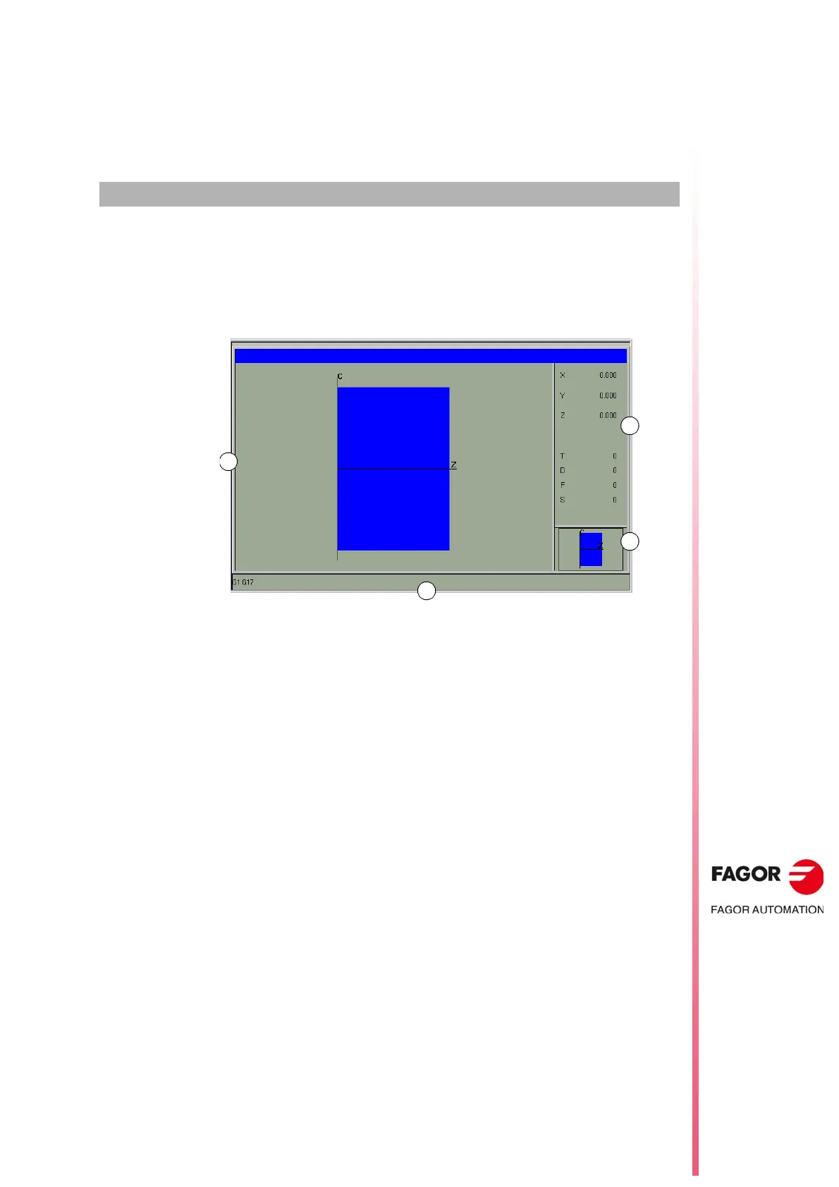
14.1 Description of the graphic environment.
The graphic environment displays a graphic representation of the program that is being
executed or simulated and take measurements on the graphics.
A Display area.
Shows a graphic representation of the tool paths or of the part as the program is being
executed or simulated.
B Dialog area.
Shows the position of the axes and the machining conditions active in the execution or
simulation (feedrate, spindle speed, tool and tool offset).
When selecting specific options of the softkey menu, it shows the information associated
with that option which may be defined by the user.
C Information area.
Shows the work plane appearing in the display area and an illustration representing the
size of the graph and the portion of the graphic area selected with the zoom.
D This area only appears during simulation and shows the "G" functions active in the
simulation.