Foundry Configuration Guide for the FESX, FSX, and FWSX
7 - 20 © Foundry Networks, Inc. December 2005
NOTE: All examples in this document assume that all ports in the illustrated topologies are point-to-point links
and are homogeneous (they have the same path cost value) unless otherwise specified.
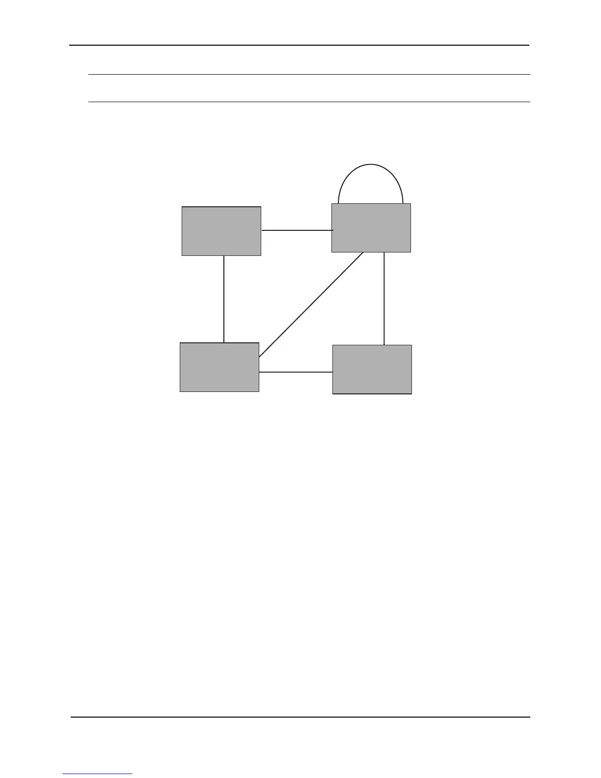
The topology in Figure 7.1 contains four bridges. Switch 1 is the root bridge since it has the lowest bridge priority.
Switch 2 through Switch 4 are non-root bridges.
Figure 7.1 Simple 802.1W Topology
Ports on Switch 1
All ports on Switch 1, the root bridge, are assigned Designated port roles.
Ports on Switch 2
Port2 on Switch 2 directly connects to the root bridge; therefore, Port2 is the Root port.
Switch 2’s bridge priority value is superior to that of Switch 3 and Switch 4; therefore, the ports on Switch 2 that
connect to Switch 3 and Switch 4 are given the Designated port role.
Furthermore, Port7 and Port8 on Switch 2 are physically connected. The RST BPDUs transmitted by Port7 are
superior to those Port8 transmits. Therefore, Port8 is the Backup port and Port7 is the Designated port.
Ports on Switch 3
Port2 on Switch 3 directly connects to the Designated port on the root bridge; therefore, it assumes the Root port
role.
The root path cost of the RST BPDUs received on Port4/Switch 3 is inferior to the RST BPDUs transmitted by the
port; therefore, Port4/Switch 3 becomes the Designated port.
Similarly Switch 3 has a bridge priority value inferior to Switch 2. Port3 on Switch 3 connects to Port 3 on Switch 2.
This port will be given the Alternate port role, since a Root port is already established on this bridge.
Ports Switch 4
Switch 4 is not directly connected to the root bridge. It has two ports with superior incoming RST BPDUs from two
separate LANs: Port3 and Port4. The RST BPDUs received on Port3 are superior to the RST BPDUs received on
port 4; therefore, Port3 becomes the Root port and Port4 becomes the Alternate port.
Port2
Port2
Port7 Port8
Port3
Port3
Port4Port4
Port3
Port2
Port3
Port4
Switch 1
Bridge priority = 100
Switch 2
Bridge priority = 200
Switch 4
Bridge priority = 400
Switch 3
Bridge priority = 300