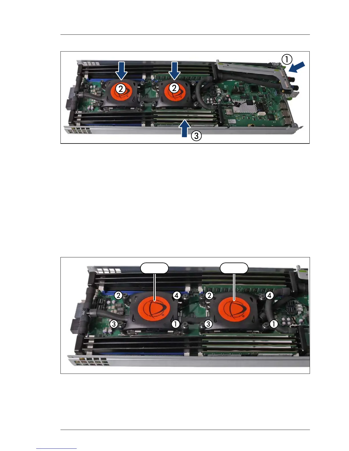
Figure 90: Installing the riser module (A)
Ê Insert the riser module with the liquid cooling kit at a slight angle (1).
Ê Carefully place the pumps (2) of the liquid cooling kit on the eight threaded
holes without fastening the screws.
Ê Carefully place the memory cooling tubes (3) between the memory slots.
I – Pay attention to the flexible tubes. The flexible tubes must not be
s
queezed by the riser module.
– For an easier installing of the liquid cooling kit disconnect the SATA
cables from the front connectors (non-PCI-side) temporally!
Figure 91: Installing the pumps
Ê First fasten the four screws for CPU 2 in a crossover pattern (1, 2, 3, 4).
Ê Second fasten the four screws for CPU 1 in a crossover pattern (1, 2, 3, 4).
 Loading...