14-6 SPARC Enterprise M4000/M5000 Servers Service Manual • December 2010
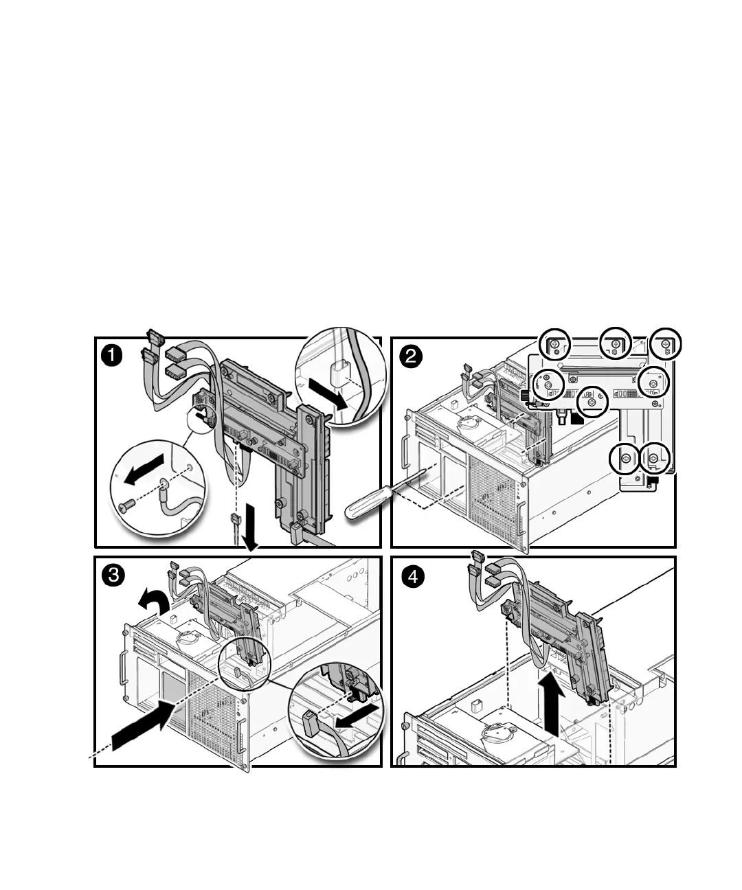
2. Loosen the eight(8) green captive screws that hold the backplane unit in
position (
FIGURE 14-3).
The screws can be accessed through the now empty power supply unit sockets.
The sockets have flaps that close for thermal reasons. If the flaps trap your hand
lift your hand upwards rather than outwards to free it.
3. Remove the backplane unit.
a. Angle the backplane unit and then pull it partially out of the server.
b. Reach one hand through the power supply opening and disconnect the grey
operator panel cable from the backplane unit.
c. Remove the backplane unit and place it on an ESD mat.
FIGURE 14-3 Removing the M4000 Server Backplane
 Loading...