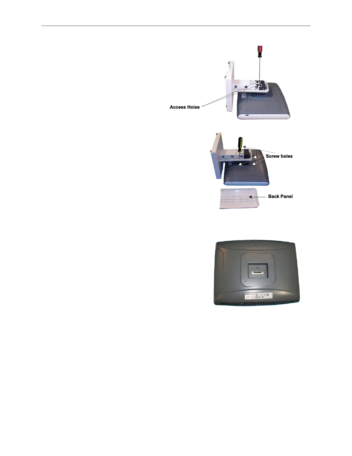
3. Pry off the back panel of the stand to expose access
holes. Use a screw driver, inserted through the
connector access holes, to assist and to gently
tighten the connector turn screws. Tighten the turn
screws until the cable connection is secure. Do not
overtighten so that it will be possible to remove the
LCD if needed.
4. Mount the stand onto the D15 using the 4
screws taped to the bottom of the stand.
There are access holes in the stand to
facilitate fastening the bottom two
mounting screws. Reattach the back
panel.
5.9.7.2 Stacked Stand Installation
1. Place the LCD face down on a clean surface. Make
sure the surface is free of anything that might
damage the screen.
90000291 Rev 3.0 5-47
TeamPoS 2000 MAINTENANCE MANUAL