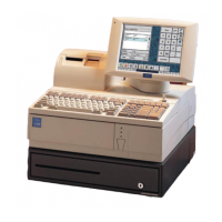
2. Unscrew the screw at the back of the protective
cover to access connector on D15.
3. Tip the stand on its front side until the cable
connector can be pushed onto the connector in the
back of the LCD. Use a screwdriver to gently
tighten the connector screws until the LCD is secure.
Do not overtighten so that it will be possible to
remove the LCD if needed. Replace protective
cover.
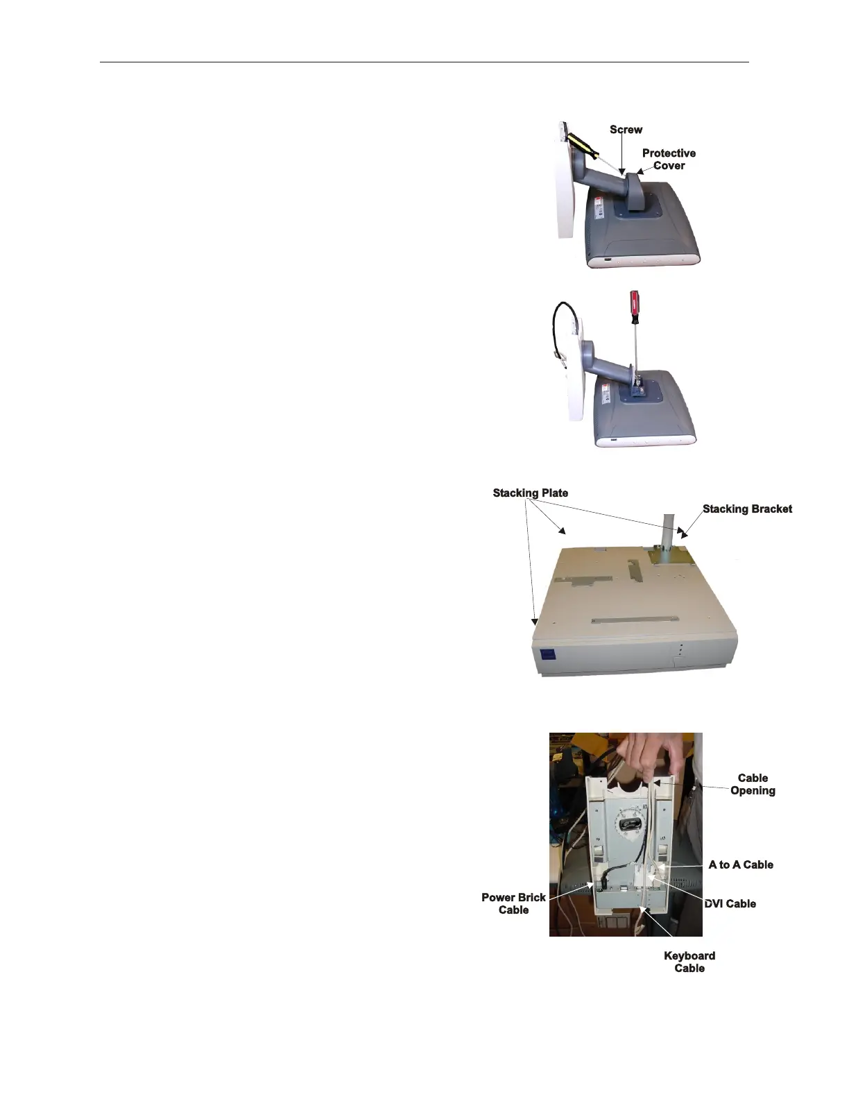
4. Install the D15 stacking plate onto the top of the
TeamPoS 2000 using thirteen M3 x 5 Phillips Flat
Head screws.
5. Install the D15 base mounting bracket using four M3
x 5 Phillips Flat Head screws with the bracket hooks
forward. The brackets for the keyboard and printer
need to be installed on the stacking plate as well.
(See D12 and A12 Stacking Bracket Locations
Section 5.1.5.)
6. Connect all the required cables to support the D15
Display, route them through the opening to one side
of the space for the pole mount, remembering to also
thread the keyboard cable under the D15.
7. Slide the D15 onto the mounting bracket.
5-48 Rev 3.0 90000291
TeamPoS 2000 MAINTENANCE MANUAL